Multi-piece fastener for limited clearance applications

a multi-piece, limited clearance technology, applied in the direction of fuselages, fastening means, fuselage frames, etc., can solve the problems of difficult installation, difficult positioning of traditional attachment methods and fasteners in such regions, and poor ergonomics

Inactive Publication Date: 2007-03-08
THE BOEING CO
View PDF27 Cites 41 Cited by
  • Summary
  • Abstract
  • Description
  • Claims
  • Application Information

AI Technical Summary

Problems solved by technology

Aerospace and military applications often provide unique challenges to design and manufacturing.
Often manufacturing requires the assembly of multiple elements within regions providing limited clearance and reduced accessibility.
Traditional attachment methodologies and fasteners may be difficult to position within such regions.
The use of traditional fasteners, such as commonly used bolt assemblies, can result in difficult installation, ergonomic issues, inconsistent torque application, and sub-optimum joint fatigue performance.
One such assembly that suffers from the aforementioned concerns is the wing side-of-body joint assembl

Method used


Image

  • Multi-piece fastener for limited clearance applications
  • Multi-piece fastener for limited clearance applications
  • Multi-piece fastener for limited clearance applications

Examples


Embodiment Construction

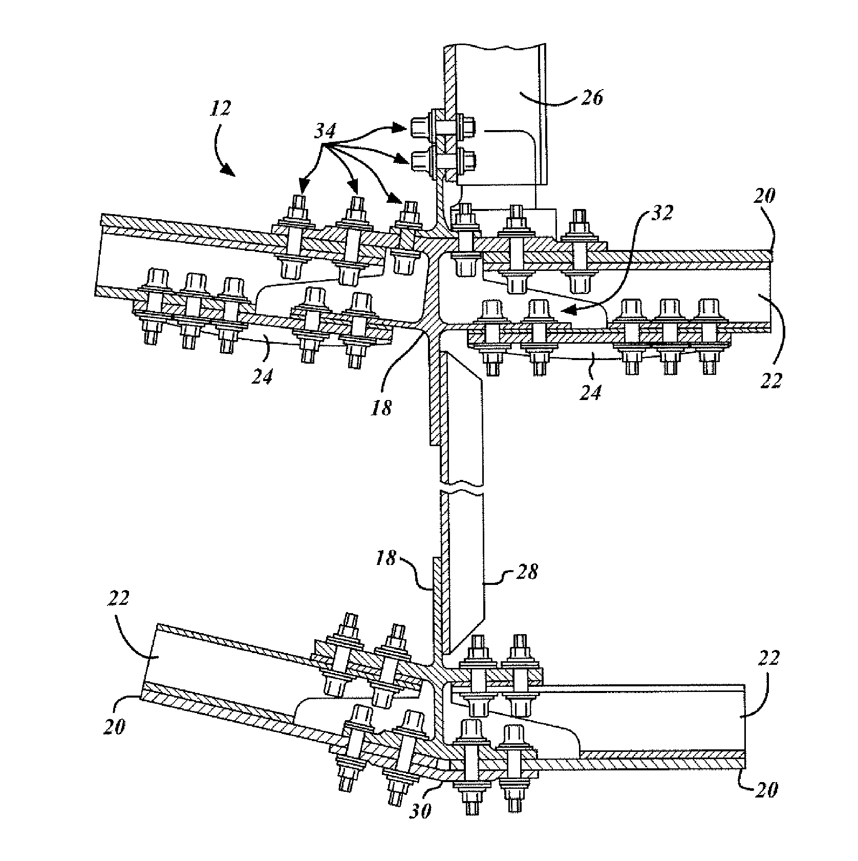
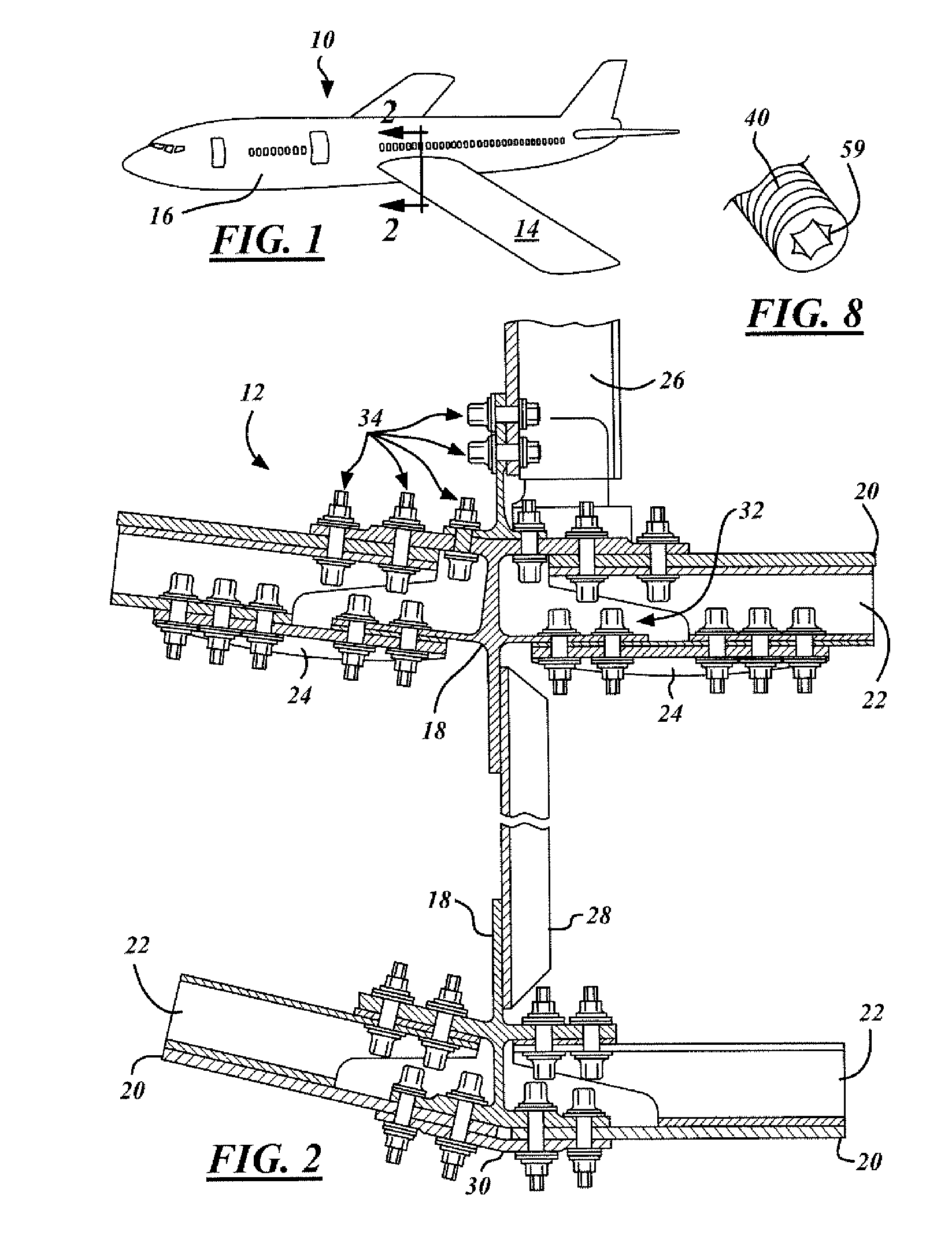
[0016] Referring now to FIG. 1, which is an illustration of an aircraft 10 in accordance with the present invention. The aircraft 10 is comprised of a plurality of joint assemblies wherein traditional fastening and assembly techniques may unfeasible or cost prohibitive. One such joint assembly is referred to as the wing side-of-body joint assembly 12, see FIG. 2. The wing side-of-body joint assembly 12 is located where the wing 14 joints the aircraft body side 16. This joint assembly 12 is very important as it is used to join a variety of structures together to form a reliable joint that is preferably highly resistant to joint fatigue.

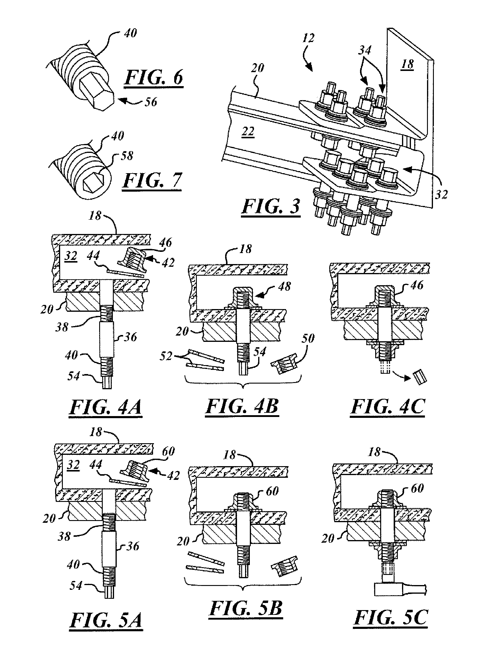
[0017] As illustrated in FIG. 2, the joint assembly 12 is used to join a variety of different structures. Aluminum or titanium chords 18, also referred to as a first joint element, are utilized to join primary structures such as aluminum or carbon fiber-reinforced composite skin elements 20, also referred to as a second joint element, stringers 22, st...


PUM


Abstract

In accordance with the present invention an aerospace wing side-of-body joint assembly is provided comprising at least one chord element, having an internal reduced clearance region, and at least one skin element. At least one cylindrical bolt assembly passes through the chord element and the skin element and secures them together. The cylindrical bolt assembly is comprised of a cylindrical stud having a threaded tail section and a threaded head section protruding into the internal reduced clearance region. A threaded head fastener inserted into the internal reduced clearance region engages the threaded head section. A nut element engages the threaded tail section and is used to introduce a torque without rotating the cylindrical stud.

Description

TECHNICAL FIELD [0001] The present invention relates generally to a method and apparatus for improving installation of joint elements in limited clearance situations, and more particularly to a method and apparatus utilizing a multi-piece fastener to secure joint elements. BACKGROUND OF THE INVENTION [0002] Aerospace and military applications often provide unique challenges to design and manufacturing. Often manufacturing requires the assembly of multiple elements within regions providing limited clearance and reduced accessibility. Traditional attachment methodologies and fasteners may be difficult to position within such regions. In addition, assembly of such structures commonly requires precise tensioning of such fasteners to minimize stresses and insure proper functioning. The use of traditional fasteners, such as commonly used bolt assemblies, can result in difficult installation, ergonomic issues, inconsistent torque application, and sub-optimum joint fatigue performance. [000...

Claims


Application Information

Patent Timeline
IPC IPC(8): B64C1/06
CPCB64C1/06F16B5/0275B64C1/26
Inventor RUFFIN, ANTONIO C.PORTER, JOHN R.
Owner THE BOEING CO
Why Eureka
Try Eureka