Suction base for an apparatus support device

a technology for supporting devices and suction bases, which is applied in the direction of suction cups, machine supports, domestic objects, etc., can solve the problems of the functioning of the suction base, affecting the movability of the suction membrane, and rendering the suction base useless

Inactive Publication Date: 2007-03-08
RSM RICHTER CHAMBERLAND
View PDF12 Cites 4 Cited by
  • Summary
  • Abstract
  • Description
  • Claims
  • Application Information

AI Technical Summary

Benefits of technology

[0005] In a suction base for the support of an apparatus, comprising a housing consisting of a hard plastic material and having an opening surrounded by a housing support edge and a suction membrane of PVC disposed in the housing so as to extend across the housing opening and being movable between a release position and an operating position in which the suction membrane is pulled into the housing and a vacuum is generated between the membrane and a support surface such that the support base is firmly pressed into contact with the support surface via the circumferential edge area of the membrane, a separating element is disposed between the housing and the suction membrane to prevent sticking of the membrane to the housing edge upon exposure of the suction base to heat and the release of plasticizer from the suction membrane.
[0006] In a particular embodiment of the invention, the separating element forms a lining of the interior housing wall of the support base and is in the form of a heat radiation reflecting element in order to mitigate the heating effects of the solar radiation.

Problems solved by technology

The attachment of such a suction base to the windshield however also results in a heavy exposure of the suction base to solar radiation.
However, at high temperatures, that is, particularly when exposed to solar radiation, some of the plasticizer is released from the PVC material of the suction membrane.
This detrimentally affects the movability of the suction membrane and the functioning of the suction base and renders the suction base useless over a period of time.

Method used


Image

  • Suction base for an apparatus support device
  • Suction base for an apparatus support device

Examples


Embodiment Construction

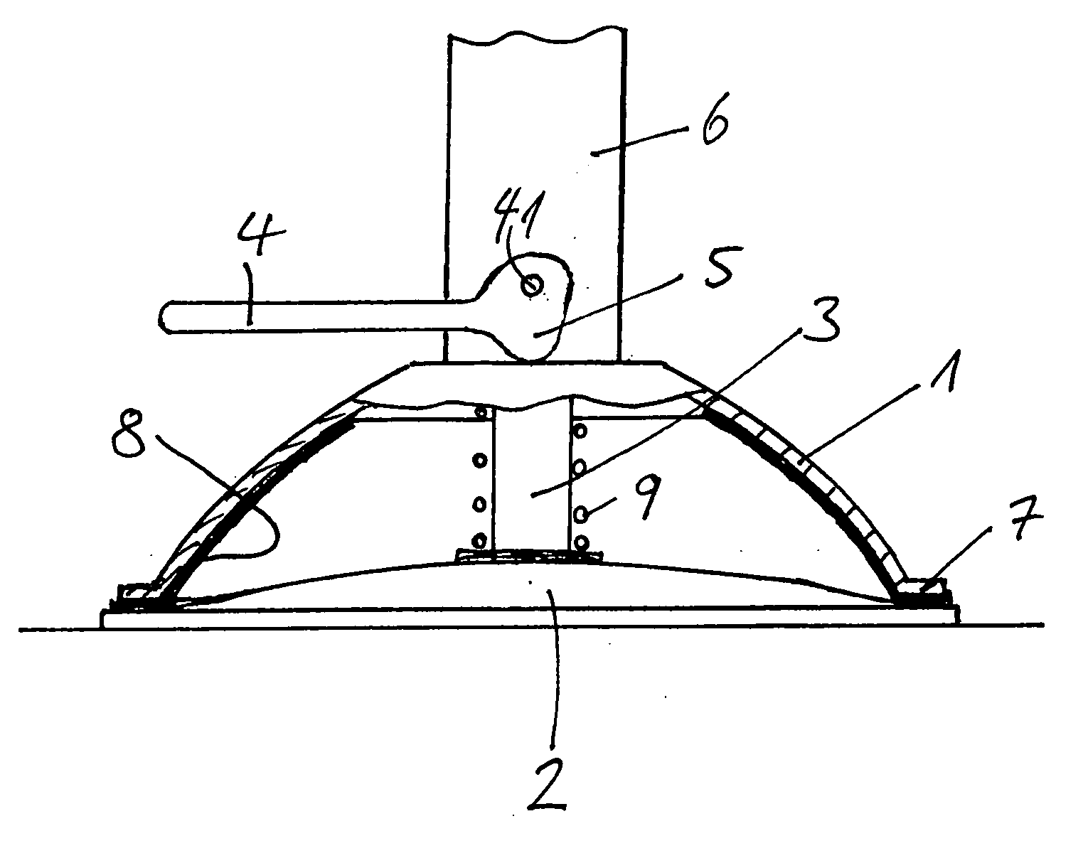
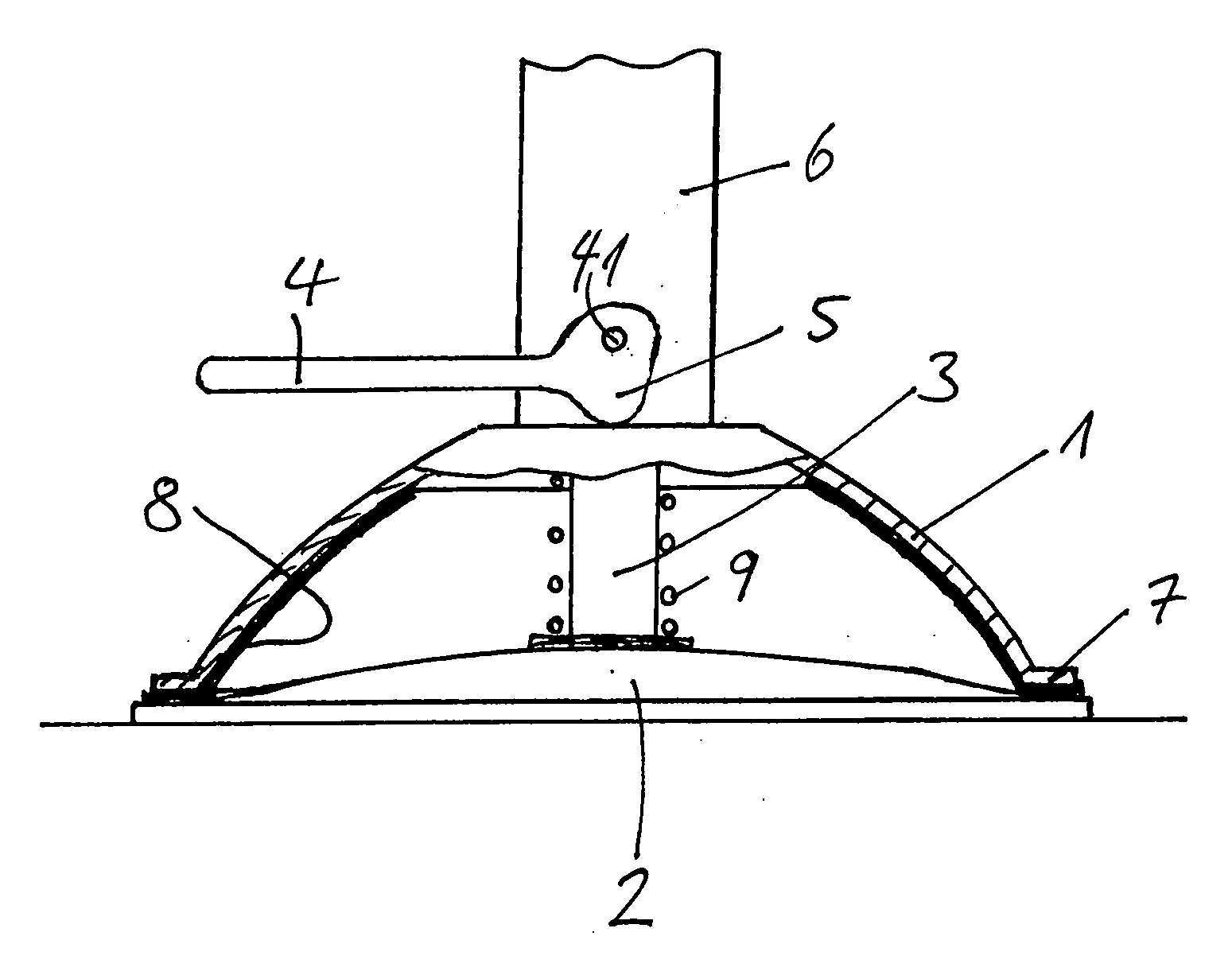
[0009] The suction base is shown schematically in the drawing in its operating position, that is, in the suction position in which the membrane is pulled into the housing 1. The housing 1 consists of a hard plastic material. In the housing 1, a suction membrane 2 of PVC is supported. An operating mechanism for the membrane 2 comprises a shaft 3 which is connected at one end to the center area of the membrane 2 and, with its other end, is pivotally connected, via a joint 41 to an operating lever 4 which is provided with an eccenter cam 5 supported on the housing 1. The housing 1 is provided, or integrally formed, with a connecting element 6 which, in the embodiment shown, is a tubular element 6 for the connection of the suction base to an other component such as a flexible support tube, generally called a goose neck. A spring 9 extends around the shaft 3 between the membrane 2 and the housing 1 for biasing the membrane 2 into its release position. However, the spring 9 may also be di...


PUM


Abstract

In a suction base for the support of an apparatus, comprising a housing consisting of a hard plastic material and having an opening surrounded by a housing support edge and a suction membrane of PVC disposed in the housing so as to extend across the housing opening and being movable between a release position and an operating position in which the suction membrane is pulled into the housing and a vacuum is generated between the membrane and a support surface such that the support base is firmly pressed into contact with the support surface via the circumferential edge area of the membrane, a separating element is disposed between the housing and the suction membrane to prevent sticking of the membrane to the housing edge upon exposure of the suction base to heat and the release of plasticizer from the suction membrane.

Description

BACKGROUND OF THE INVENTION [0001] The invention relates to a suction base for an apparatus support device as used for example in motor vehicles for supporting minicomputers (so-called PDA's), mobile navigation apparatus, mobile telephones and similar devices on smooth surfaces such as the windshield of the motor vehicle. The windshields provide a perfectly smooth surface suitable for the attachment of a suction base for supporting a particular apparatus in the field of view of a driver. [0002] The attachment of such a suction base to the windshield however also results in a heavy exposure of the suction base to solar radiation. The suction base generally consists of a housing of rigid plastic material and a suction membrane of a soft plastic which forms the bottom or connecting end of the suction base. The suction membrane is provided at its center with the shaft of an operating mechanism by which the suction membrane is movable, by means of an operating lever between a release pos...

Claims


Application Information

Patent Timeline
Patent Type & Authority Applications(United States)
IPC IPC(8): F16B47/00
CPCF16B47/00B60R2011/0056F16B47/006
Inventor RICHTER, HARALD
Owner RSM RICHTER CHAMBERLAND
Why Eureka
Try Eureka