In-plane switching mode liquid crystal display and method for manufacturing the same

a liquid crystal display and switching mode technology, applied in non-linear optics, instruments, optics, etc., can solve the problems of weak light leakage, excessive light leakage, and poor performance, and achieve the effect of reducing the aperture ratio, improving the contrast ratio, and reducing the increase in the black level

Active Publication Date: 2007-03-08
LG DISPLAY CO LTD
View PDF12 Cites 20 Cited by
  • Summary
  • Abstract
  • Description
  • Claims
  • Application Information

AI Technical Summary

Benefits of technology

[0012] An object of the present invention, in part, is to provide an in-plane switching mode liquid crystal display and a method for manufacturing the same that can prevent light leakage to the maximum without reducing an aperture ratio.
[0013] Another object of the present invention, in part, is to provide an in-plane switching mode liquid crystal display and a method for manufacturing the same that can improve the contrast ratio by reducing the increase in the black level due to light leakage.

Problems solved by technology

However, in the related art liquid crystal display, when a side surface of a pixel area has a bent structure to correspond to a form of the common electrode and the pixel electrode, a step in which a rubbing processing is well performed and a step in which a rubbing processing is not well performed are inevitably generated in a side surface of a pixel area.
In this case, when the rubbing processing is performed well, as when the liquid crystal material is uniformly aligned, light leakage is weak.
In contrast, when rubbing processing is not performed well, as in a liquid crystal material that is not uniformly aligned, light leakage is excessive.
Accordingly, because light leakage increases the black level, there is a problem in that the contrast ratio deteriorates.
However, since the line width of the black matrix is excessively widened, there is a problematic decrease of the aperture ratio resulting in that the brightness decreases.

Method used


Image

  • In-plane switching mode liquid crystal display and method for manufacturing the same
  • In-plane switching mode liquid crystal display and method for manufacturing the same
  • In-plane switching mode liquid crystal display and method for manufacturing the same

Examples


Embodiment Construction

[0025] Other objects and advantages of the invention will be apparent through descriptions or with reference to the accompanying drawings. Like reference numerals designate like elements throughout the specification.

[0026] Hereinafter, an in-plane switching mode liquid crystal display and a method for manufacturing the same according to an embodiment of the invention will be described in detail with reference to the accompanying drawings.

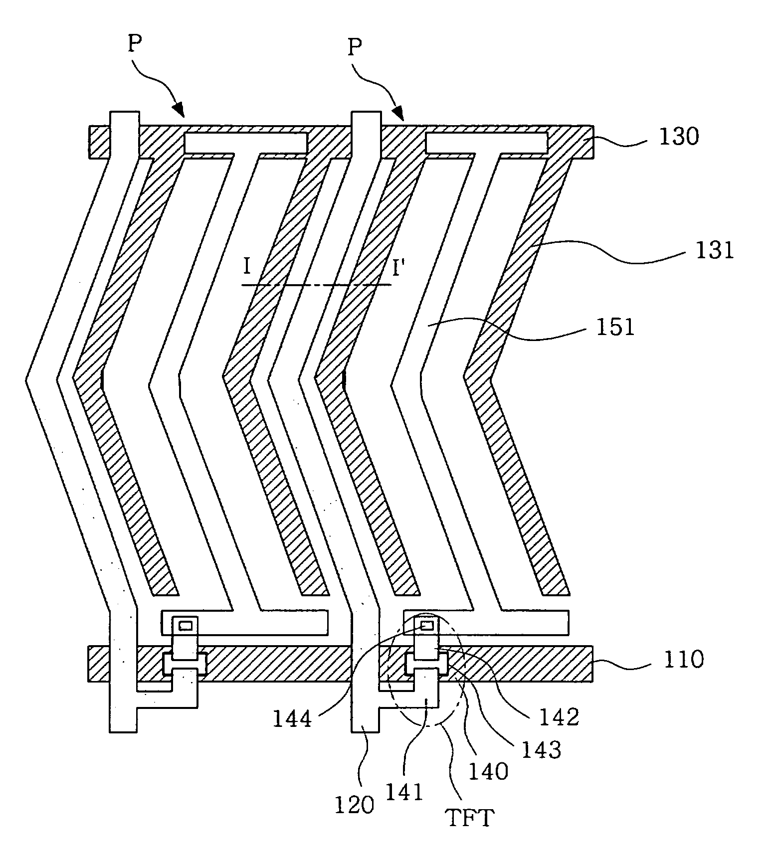
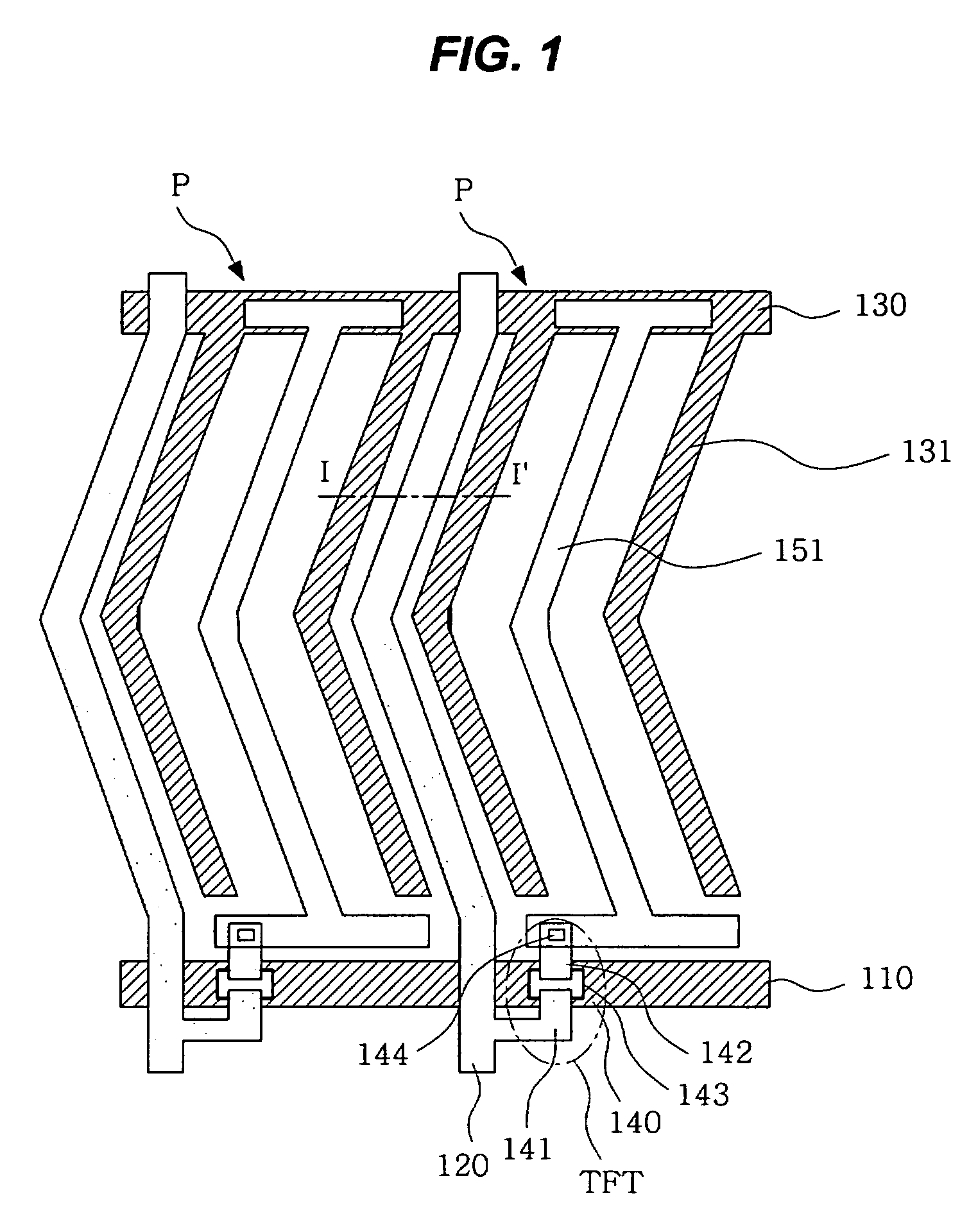
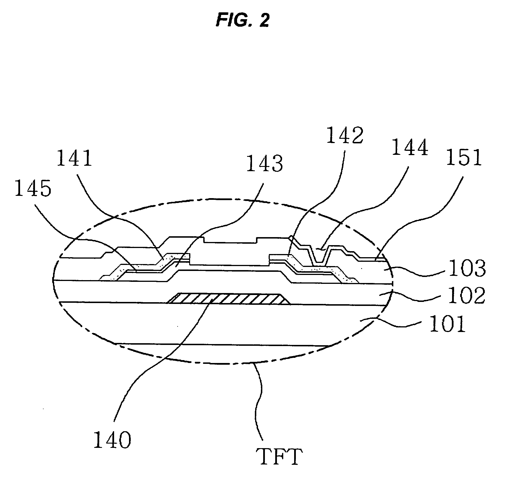
[0027]FIG. 1 shows a top plan view illustrating some of a pixel area of an in-plane switching mode liquid crystal display according to an embodiment. FIG. 2 shows a cross-sectional view illustrating in more detail a thin film transistor of FIG. 1. FIG. 3 shows a cross-sectional view schematically illustrating plane I-I′ of FIG. 1.

[0028] Referring to FIGS. 1 to 3, the in-plane switching mode liquid crystal display according to an embodiment includes a TFT array substrate 100, a color filter array substrate 200, and a liquid crystal layer 300 that ...


PUM

PropertyMeasurementUnit
areaaaaaaaaaaa
widthaaaaaaaaaa
transparentaaaaaaaaaa

Abstract

A liquid crystal display and a method of manufacturing the same that can reduce the increase in the black level due to light leakage, without reducing the aperture ratio while improving the contrast ratio. The liquid crystal display includes a TFT array substrate comprising a data line, a pixel electrode and a common electrode, and the data line, the pixel electrode and the common electrode have at least one bent structure; a color filter array substrate opposite to the TFT array substrate, the color filter array substrate comprising a black matrix covering an area corresponding to at least the data line and the common electrode; and a liquid crystal layer formed between the TFT array substrate and the color filter array substrate, wherein the black matrix comprises a first black matrix line covering an area where light leakage is minimal, and a second black matrix line covering an area where light leakage is excessive, the second black matrix having a line width larger than a line width of the first black matrix.

Description

[0001] This Nonprovisional Application claims priority under 35 U.S.C. §119(a) of Patent Application Nos. 10-2005-0080970 and 10-2006-0009271 filed in Korea on Aug. 31, 2005 and Jan. 31, 2006, respectively, the entire contents of which are hereby incorporated by reference. BACKGROUND OF THE INVENTION [0002] 1. Field of the Invention [0003] The invention relates to a liquid crystal display and a method for manufacturing the same, and more particularly, to an in-plane switching (IPS) mode liquid crystal display and a method for manufacturing the same. [0004] 2. Description of the Background Art [0005] A liquid crystal display changes the molecular arrangement of the liquid crystal material by controlling the intensity of an electric field by applying different potentials to a pixel electrode and a common electrode encompassing a liquid crystal layer having dielectric anisotropy. A typical display includes a color filter array substrate in which a common electrode, a color filter, a bl...

Claims


Application Information

Patent Timeline
Patent Type & Authority Applications(United States)
IPC IPC(8): G02F1/1343
CPCG02F1/134363G02F1/133512
Inventor CHO, SUK HOPARK, SU JUNGKIM, JIN HO
Owner LG DISPLAY CO LTD
Why Eureka
Try Eureka