Optical scanning device
- Summary
- Abstract
- Description
- Claims
- Application Information
AI Technical Summary
Benefits of technology
Problems solved by technology
Method used
Image

Examples
first embodiment
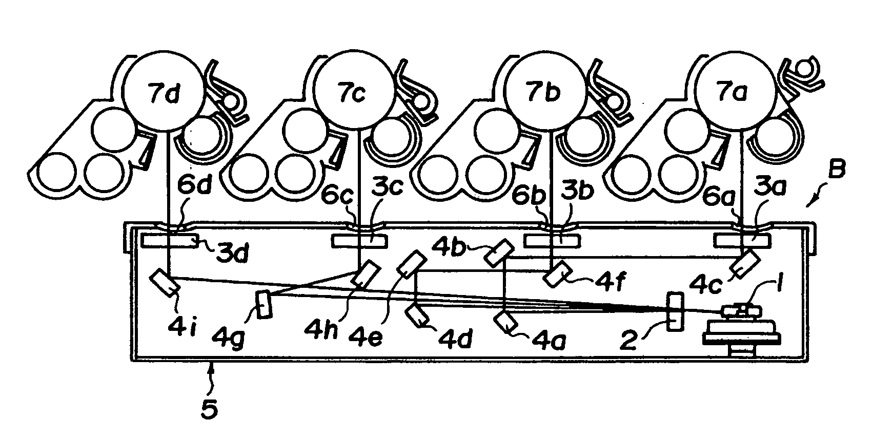
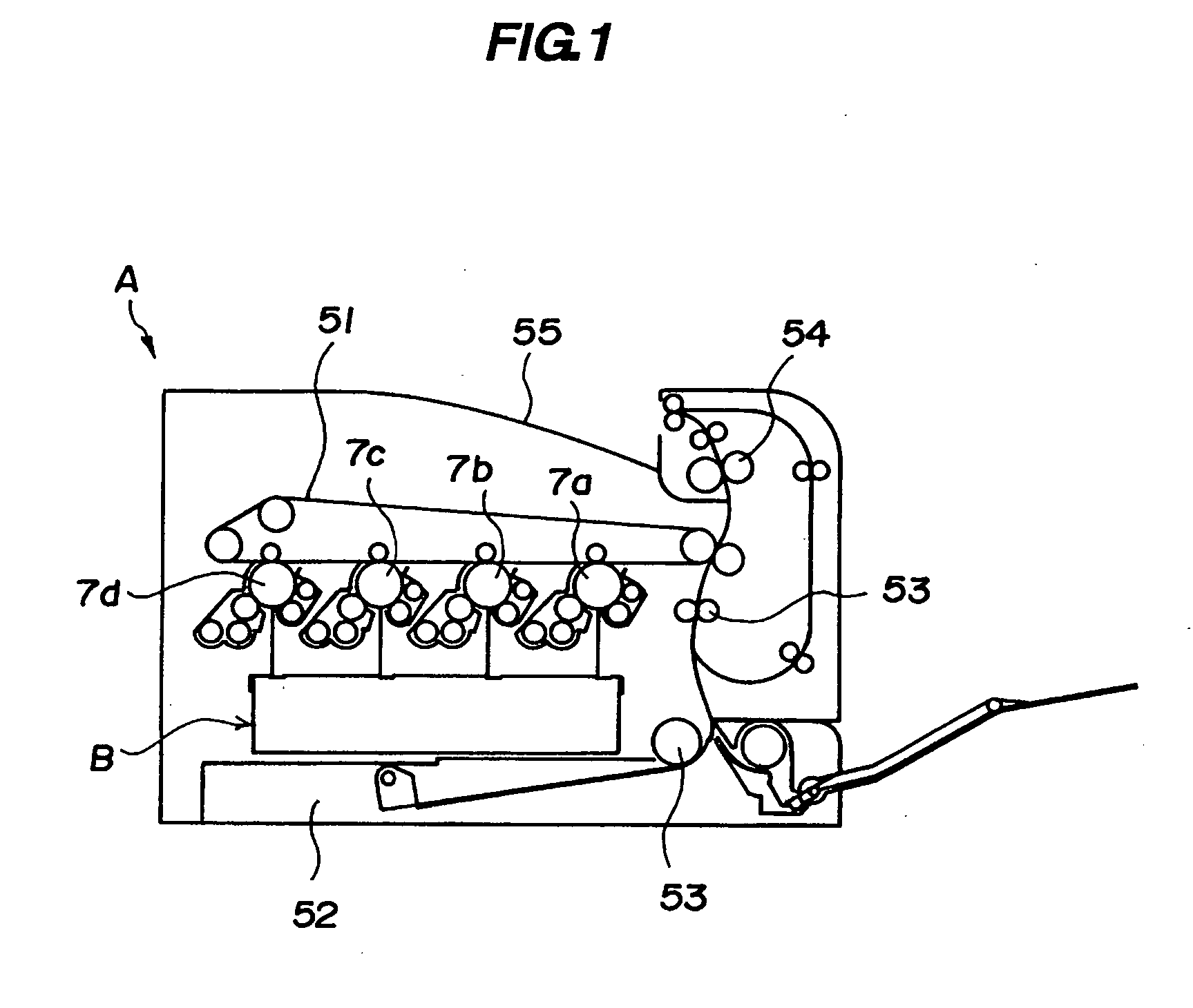
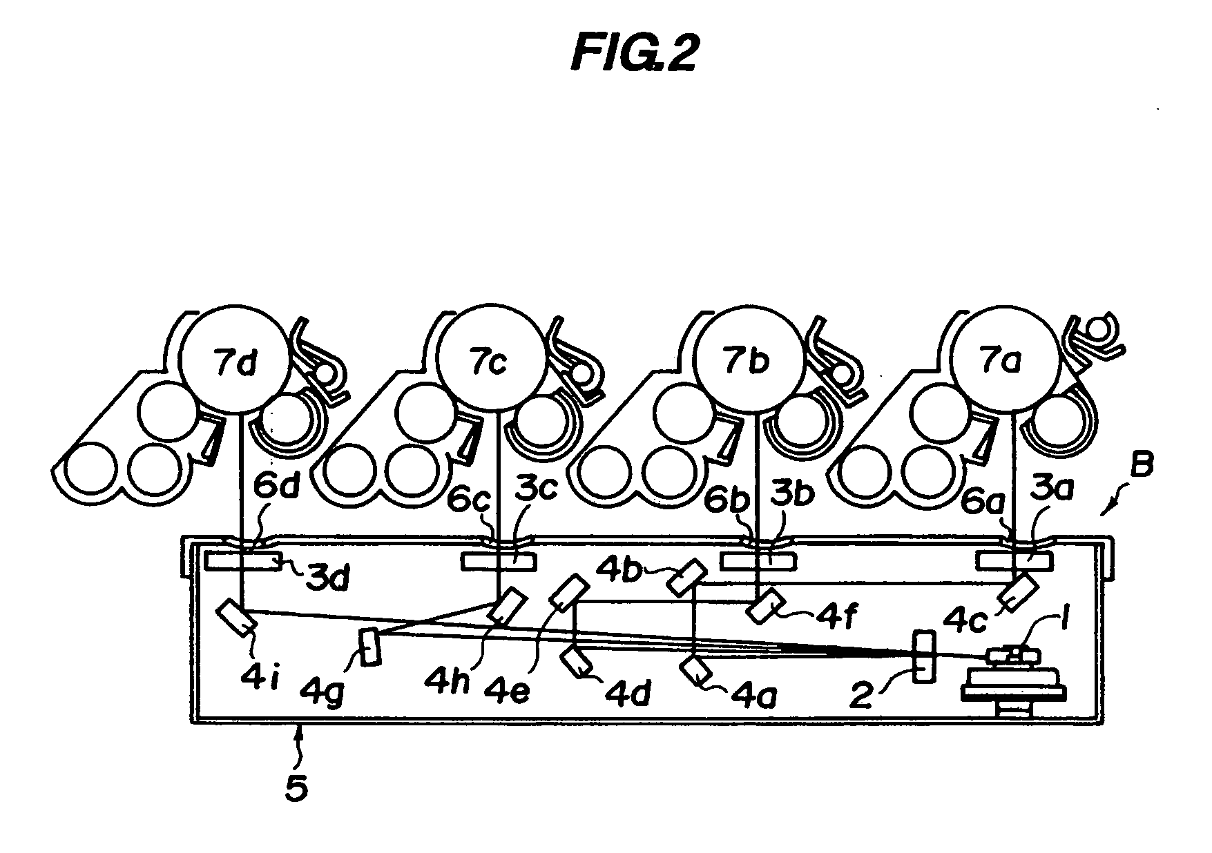
[0035] A scanning optical device and an image forming apparatus according to a first embodiment will be described below with reference to FIGS. 1 to 4. FIG. 1 is a pattern sectional diagram showing an entire configuration of the image forming apparatus, FIGS. 2 and 3 are sectional diagrams for explaining the scanning optical device, and FIGS. 4 and 5 are sectional diagrams for explaining a scanning optical device having a plurality of scanning groups.
(Entire Configuration of Image Forming Apparatus)
[0036] An entire configuration of an image forming apparatus having a scanning optical device will be described below together with an image forming operation with reference to FIG. 1. FIG. 1 shows an image forming apparatus A which prints a color image. In the image forming apparatus A, four photosensitive drums 7a to 7d serving as image bearing members independently set to colors, i.e., yellow, magenta, cyan, and black are arranged in parallel to each other. A charging means which el...
second embodiment
[0058] A device according to a second embodiment will be described below with reference to FIGS. 4 and 5. Since the basic configuration of the device according to this embodiment is the same as that of the embodiment described above, a repetitive explanation is omitted. A configuration which is a characteristic feature of the embodiment will be described below.
[0059] A scanning optical device B using an image forming apparatus may expose a plurality of photosensitive drums by using an oblique incident optical system. In particular, all the photosensitive drums need not be exposed by one polygon mirror.
[0060] In FIG. 4, in an image forming apparatus in which six photosensitive drums 8a to 8f are arranged, two adjacent photosensitive drums are exposed by one scanning optical device B, and the six photosensitive drums 8a to 8f are exposed by three scanning optical devices B. In FIG. 5, three adjacent photosensitive drums are exposed by one scanning optical device B, and six photosens...
third embodiment
[0066] A device according to a third embodiment will be described below with reference to FIG. 6. Since the basic configuration of the device according to the embodiment is the same as that of the embodiment described above, a repetitive explanation is not described. A configuration which is a characteristic feature of the embodiment will be described below.
[0067] In a scanning optical device C used in the embodiment, the following system is used. That is, three laser beams are incident on both sides of one polygon mirror 10 to expose six photosensitive drums 9a to 9f. Optical paths to the photosensitive drums 9a to 9f of the scanning optical device C are horizontally symmetrical about the polygon mirror 10. For this reason, although an image scanning group A on the right in FIG. 6 will be described with reference to FIG. 6, an image scanning group B on the left side has the same configuration as that of the image scanning group A.
PUM
 Abstract
Description
Claims
Application Information