Color wheel
a color wheel and wheel body technology, applied in the field of optical elements, can solve problems such as the stability of the assembling of the color wheel, and achieve the effects of increasing the assembling stability of the color filter set, increasing the connection force, and increasing the assembling stability of the color wheel
- Summary
- Abstract
- Description
- Claims
- Application Information
AI Technical Summary
Benefits of technology
Problems solved by technology
Method used
Image

Examples
first embodiment
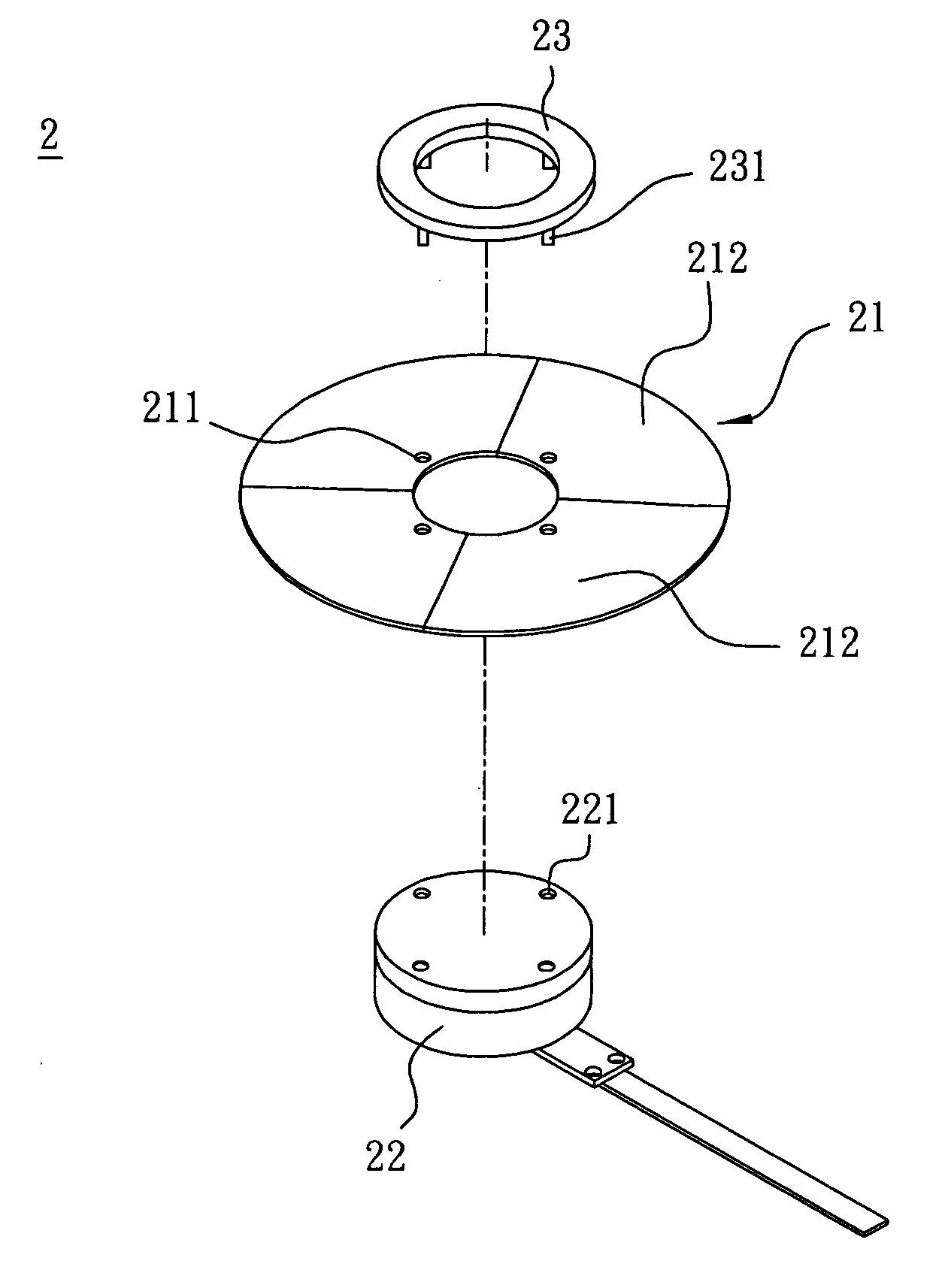
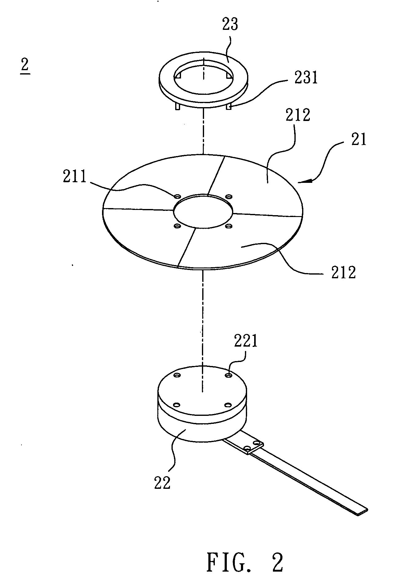
[0025] Referring to both FIGS. 2 and 3, a color wheel 2 according to a first embodiment of the invention includes a color filter set 21, a carrier 22 and a cap 23.
[0026] The color filter set 21 has at least one through hole 211, or preferably more than through hole 211, as long as these through hole are symmetrically arranged on the color filter set 21. In this embodiment, the color filter set 21 is a flat ring-shaped structure constituted by one or more color filter sheets 212. Preferably, each color filter sheets 212 has a through hole 211. The color filter set 21 has a first side 213 and a second side 214 which is oppositely disposed to the first side 213. Herein, the color filter set 21 is connected to the carrier 22.
[0027] The carrier 22 is disposed at the first side 213 of the color filter set 21 and has at lease one first engaging portion 221, such as an indention, corresponding to the through hole 211. Herein, there are four indentations 221 disposed on the carrier 22 and ...
second embodiment
[0031] Referring to FIG. 4, a color wheel 2′ of a second embodiment of the invention includes a color filter set 21, a carrier 22′ and a cap 23′. In this embodiment, the functions and the features of the color filter set 21 are same as those of the color filter set 21 in the first embodiment, detailed description thereof will be omitted.
[0032] The carrier 22′ is disposed at the first side 213 of the color filter set 21 and has at lease one first engaging portion 221′, such as a protrusion, corresponding to the through hole 211. Herein, there are four protrusions 221′ disposed on the carrier 22′ and facing the color filter set 21.
[0033] The cap 23′ is disposed at the second side 214 of the color filter set 21 and has at lease one second engaging portion 231′, such as an indention, corresponding to the through hole 211 and the first engaging portion 221′. Herein, the cap 23′ has four indentions 231′ for being connected with the first engaging portion 221′.
[0034] The protrusion 221′...
third embodiment
[0036] As shown in FIG. 5, a color wheel 3 of a third embodiment of the invention includes a color filter set 31, a carrier 32 and at least one fastening element 33. The color filter set 31 has at least one through hole 311, or preferably more than through hole 311, as long as these through hole are symmetrically arranged on the color filter set 31. In this embodiment, the color filter set 31 is a flat ring-shaped structure constituted by one or more color filter sheets. Preferably, each color filter sheets has a through hole 311. The color filter set 31 has a first side 313 and a second side 314 which is oppositely disposed to the first side 313. Herein, the color filter set 31 is connected to the carrier 22.
[0037] The carrier 32 is disposed at the first side 313 of the color filter set 31 and has a first indention 321 corresponding to the through hole 311 of the color filter set 31. Herein, there are at least two first indentations 321 disposed on the carrier 32 and facing the co...
PUM
 Abstract
Description
Claims
Application Information