Semiconductor memory device

a memory device and semiconductor technology, applied in the direction of information storage, static storage, digital storage, etc., can solve the problems of complex circuits, inability to perform refresh immediately when refresh becomes possible, and inability to prevent read instructions or write instructions from being sent, so as to increase the efficiency of external access and the effect of refresh

Inactive Publication Date: 2007-03-08
IBM CORP
View PDF3 Cites 4 Cited by
  • Summary
  • Abstract
  • Description
  • Claims
  • Application Information

AI Technical Summary

Benefits of technology

[0024] According to the refresh control method, the refresh is immediately performed while giving priority to the external access, based on the states of the busy signal for indicating that the array control circuit is in operation, the access waiting signal for indicating that the external access is requested, and the refresh waiting signal for indicating that the refresh is requested. Thus the efficiency of the external access and the refresh can be increased.

Problems solved by technology

However, since dynamic memory cells have neither driving capability nor restoring capability, DRAMs need to perform refresh operations to read data and write the same data back within a specified refresh period in order to prevent memory loss due to leakage current and so forth.
In this case, since refresh operations may possibly compete with normal read operations or write operations, refresh operations need to be controlled so that refresh operations may not prevent read instructions or write instructions sent from external devices.
In any of the aforementioned methods, the control is complicated, and thus the circuits are complicated.
Moreover, in any of the methods, since operations are controlled only by arbitration between external accesses and internally generated refresh requests, refresh cannot be performed immediately when refresh becomes possible.
For that reason, efficiency of refresh is low.

Method used


Image

  • Semiconductor memory device
  • Semiconductor memory device
  • Semiconductor memory device

Examples


first embodiment

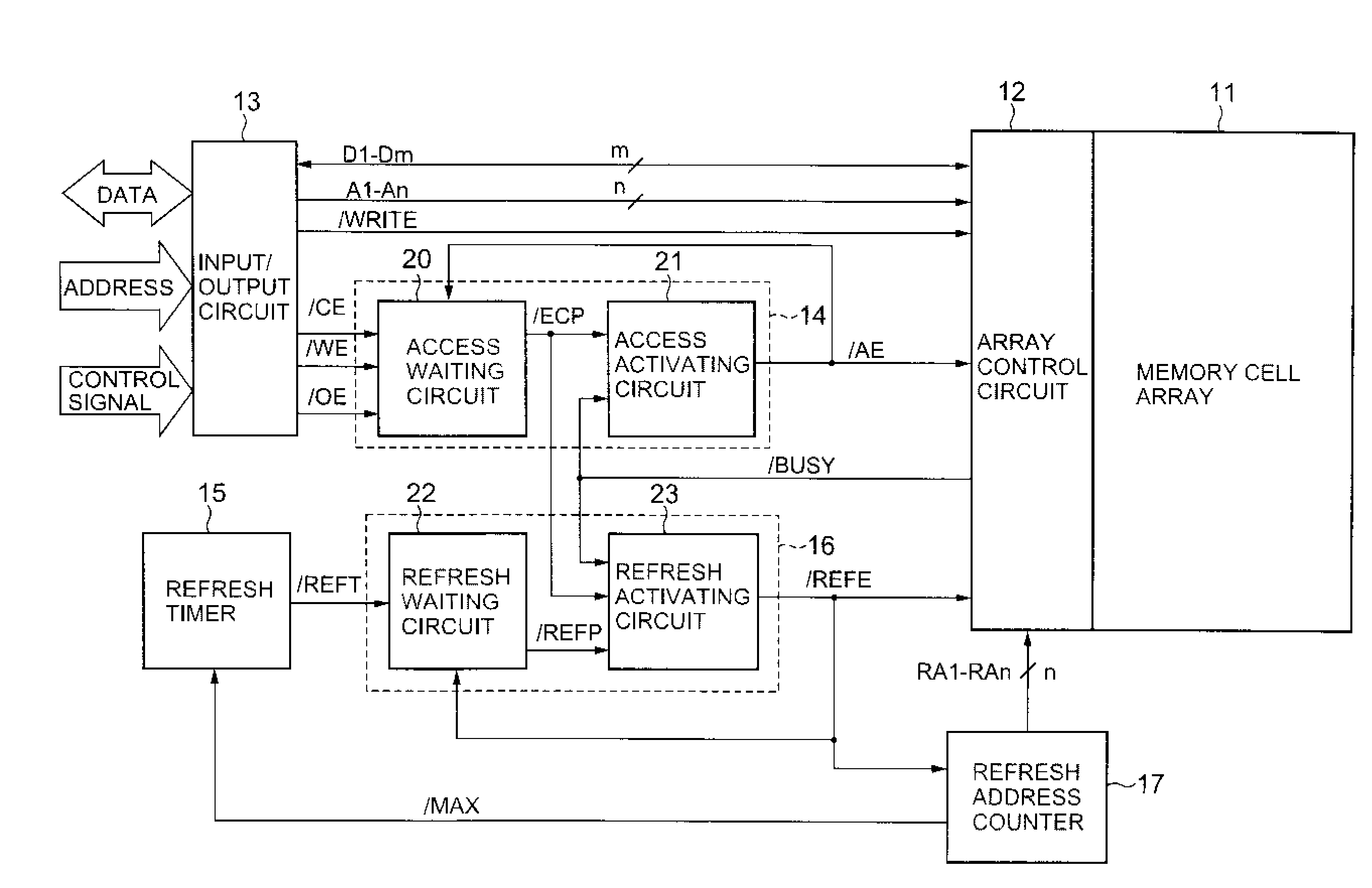
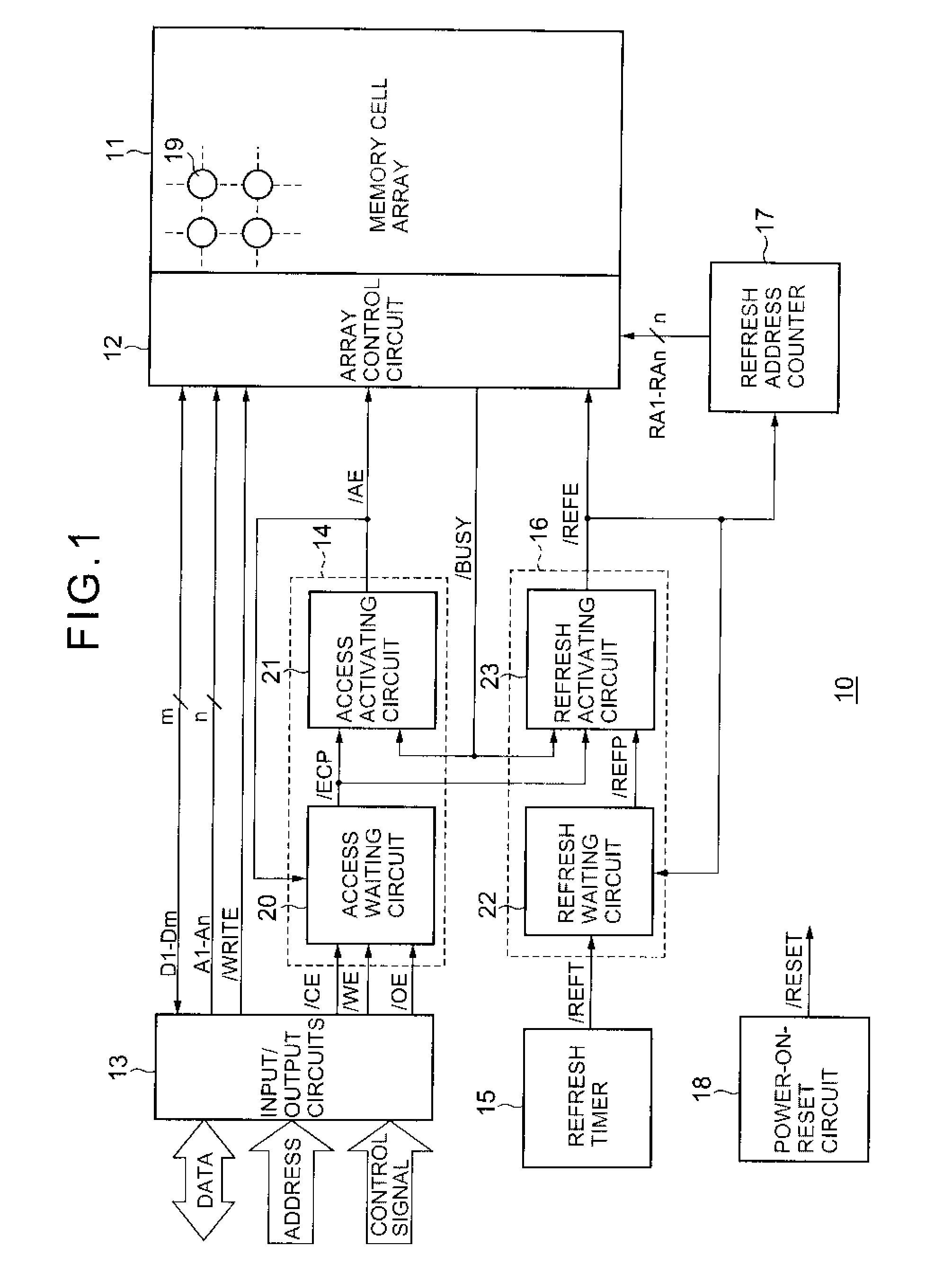
[0034] Referring to FIG. 1, pseudo SRAM 10 according to a first embodiment of the present invention includes a memory cell array 11, an array control circuit 12, input / output circuits 13, an access control circuit 14, a refresh timer 15, a refresh control circuit 16, a refresh address counter 17, and a power-on reset circuit 18.

[0035] The memory cell array 11 includes a plurality of dynamic memory cells 19 arranged in matrix form. Each dynamic memory cell 19 consists of a transistor (not shown) and a capacitor (not shown), and stores 1 bit data by charging electric charge in the capacitor. The memory cell array 11 further includes a plurality of word lines (not shown) arranged in rows, and a plurality of bit line pairs (not shown) arranged in columns. The dynamic memory cells 19 are arranged at positions corresponding to intersections of word lines and bit line pairs.

[0036] The array control circuit 12 accesses the memory cell array 11 according to external address signal A1-An of...

second embodiment

[0066] Referring to FIG. 7, in the second embodiment of the present invention, unlike the aforementioned first embodiment, the refresh address counter 17 generates a refresh completion signal / MAX, when it finishes generating the last refresh address signal RA1-RAn. The refresh timer 15 keeps the refresh request signal / REFT at L level until the refresh completion signal / MAX is set to L level.

[0067] Next, burst refresh operation according to the second embodiment will be described.

[0068] Referring to FIG. 8, and in particular, part (a) of FIG. 8, when the refresh timer 15 brings the refresh request signal / REFT to L level, the refresh waiting circuit 22 will bring the refresh waiting signal / REFP to L level. Unlike the aforementioned first embodiment, the refresh timer 15 keeps the refresh request signal / REFT at L level until the refresh completion signal / MAX is set to L level. Therefore, when the refresh activating signal / REFE is set to L level, the RS flip-flop circuit 37 of...


PUM


Abstract

Pseudo SRAM capable of arbitrating refresh requests with external access requests is provided. An access waiting circuit 20 for generating an access waiting signal /ECP in response to an external access request signal /CE or the like, an access activating circuit 21 for generating an access activating signal /AE in response to L level of the access waiting signal /ECP and H level of a busy signal /BUSY, a refresh waiting circuit 22 for generating a refresh waiting signal /REFP in response to a refresh request signal /REFT, and a refresh activating circuit 23 for generating a refresh activating signal /REFE in response to H level of the access waiting signal /ECP, L level of the refresh waiting signal /REFP, and H level of the busy signal /BUSY are provided. An array control circuit 12 performs an access operation in response to the access activating signal /AE, and performs the refresh operation in response to the refresh activating signal /REFE.

Description

CROSS REFERENCE TO RELATED PUBLICATIONS [0001] This patent application claims priority to Japanese Patent Application No. 2005-254878 filed Sep. 2, 2005. FIELD OF THE INVENTION [0002] The present invention relates to a semiconductor memory device, and more specifically, it relates to pseudo SRAM (PSRAM; Pseudo Static Random Accesses Memory) and DRAM (Dynamic Random Accesses Memory), both of which require refresh operations. BACKGROUND OF THE INVENTION [0003] Conventionally, SRAM (Static Random Accesses Memory) and DRAM have been widely used as rewritable semiconductor memory devices. [0004] SRAM uses static memory cells and a static memory cell usually consists of six transistors. Since static memory cells have driving capability and restoring capability, SRAM is mainly used for high-speed applications. [0005] On the other hand, DRAM uses dynamic memory cells and a dynamic memory cell usually consists of one transistor and one capacitor. Since dynamic memory cells are small in size,...

Claims


Application Information

Patent Timeline
Patent Type & Authority Applications(United States)
IPC IPC(8): G11C7/00
CPCG11C11/406G11C11/40615G11C11/40603
Inventor MIYATAKE, HISATADA
Owner IBM CORP
Why Eureka
Try Eureka