Check patentability & draft patents in minutes with Patsnap Eureka AI!

Coding in a MIMO communication system

a communication system and multi-output technology, applied in the field of multi-input multi-output (mimo) communication systems, can solve the problems that the use of pilot beams is not convenient in all mimo communication systems, and the use of such pilot beams may not enable the measurement of the transmission matrix

Active Publication Date: 2007-03-08
ALCATEL-LUCENT USA INC
View PDF3 Cites 8 Cited by
  • Summary
  • Abstract
  • Description
  • Claims
  • Application Information

AI Technical Summary

Problems solved by technology

Unfortunately, the use of pilot beams is not convenient in all MIMO communication systems.
For example, the uses of such pilot beams may not be enable measurements of the transmission matrix, H, for a channel whose properties are changing rapidly.

Method used


Image

  • Coding in a MIMO communication system
  • Coding in a MIMO communication system
  • Coding in a MIMO communication system

Examples


Embodiment Construction

1. MIMO Communication System

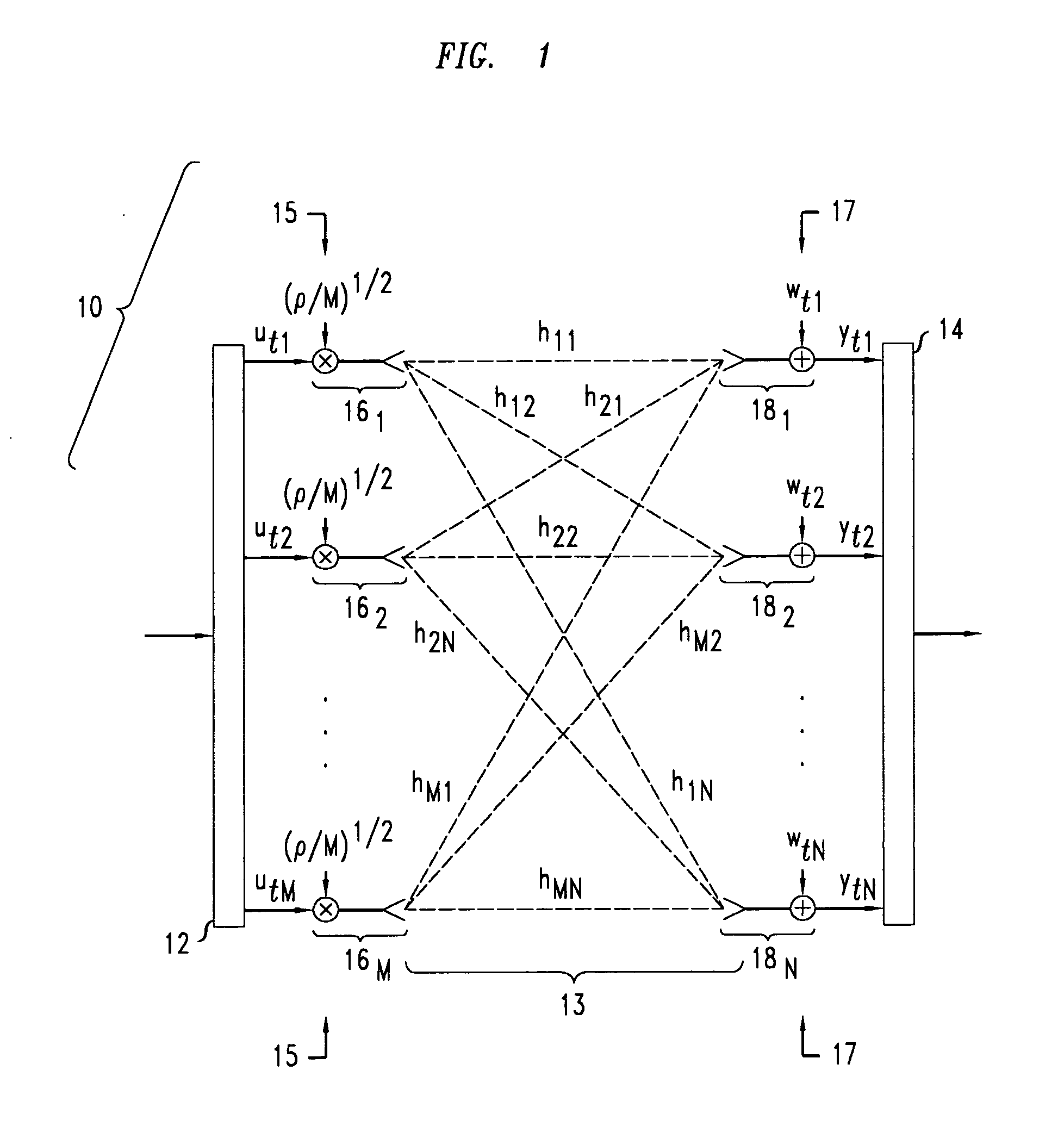
[0017]FIG. 1 illustrates a multiple-input-multiple-output (MIMO) communication system 10. The system includes a transmitter 12, a communication channel 13, and a receiver 14. The transmitter 12 has an array 15 of M transmission antennas 161, . . . , 16M. The channel 13 is, e.g., typically a free-space channel with a number of signal-scatterers therein (not shown). The receiver 14 has an array 17 of reception antennas 181, . . . , 18N. The transmission and reception arrays 15, 17 may have the same or different numbers of antennas. That is, the positive integers “M” and “N” may be equal to or different. The number M is greater than 1 for a MIMO transmitter and is, e.g., preferably equal to 2m−1 where “m” is a positive integer greater than 1, e.g., m=2, 3, 4, 5, 6, 7, 8, 9, 10, or more.

[0018] The characteristics of the MIMO communication system 10 include transmission gains, a T×N-dimensional noise matrix w, and an M×N transmission matrix H. The transmiss...


PUM


Abstract

A method of receiving information includes receiving a vector of signal values for a transmitted codeword in antennas of a MIMO receiver array in each of a sequence of time slots. Each vector forms one row of a matrix Y. Each antenna receives the signal values of one column of the matrix Y over the sequence of time slots such that one of the antennas receives the signal values of each column of the matrix Y. The method also includes evaluating a vector S (0, . . . , 0) for an associated zero m-component vector (0, . . . , 0). The vector S (0, . . . , 0) is given by a Hadamard transform of the diagonal part of the square matrix Y·Y†.

Description

BACKGROUND [0001] This is a continuation-in-part application of application Ser. No. 11 / 219,126, filed Sep. 2, 2005. FIELD OF THE INVENTION [0002] The invention relates to multiple-input-multiple-output (MIMO) communication systems and methods of operating MIMO systems. DISCUSSION OF THE RELATED ART [0003] A MIMO communication system includes a transmitter with multiple transmitting antennas, a receiver with multiple receiving antennas, and a free space channel coupling the transmitting and receiving antennas. The transmitting antennas transmit on the same frequency band in each time slot. For that reason, a transmitter having M transmitting antennas can be viewed as sending a row of M signal values in each time slot. If the transmitter transmits a message over T time slots, the message is associated with a T×M dimensional matrix, U, of signal values. [0004] The free space channel couples the multiple transmitting antennas to various ones of the receiving antennas. Thus, in each tim...

Claims


Application Information

Patent Timeline
IPC IPC(8): H04L1/02H04L27/00
CPCH04L1/0612H04B7/0413
Inventor ASHIKHMIN, ALEXEI
Owner ALCATEL-LUCENT USA INC
Features
  • R&D
  • Intellectual Property
  • Life Sciences
  • Materials
  • Tech Scout
  • Unparalleled Data Quality
  • Higher Quality Content
  • 60% Fewer Hallucinations
Learn More