
Magnetic needle positioner

a magnetic needle and positioner technology, applied in the field of surgical instruments, can solve the problems of requiring significant additional training of the physician, calibration and maintenance procedures, and the inability to afford to provide this complex device, and achieve the effect of simple method and mechanism to control the positioning of the suture needl

Inactive Publication Date: 2007-03-08
GIAP BRANDON
View PDF21 Cites 62 Cited by
  • Summary
  • Abstract
  • Description
  • Claims
  • Application Information

AI Technical Summary

Benefits of technology

[0017] There exists in medicine today a need for a simple method and mechanism to effect control and positioning of the suture needle during surgery that is inexpensive, does not require specialized equipment other than that which might be present in a nominally equipped hospital surgery, and does not imply additional training and specialization on the part of the physician.
[0018] It is thus the object of the present invention to provide a simple to use, inexpensive device that is readily incorporated into a previously learned surgical procedure such as suturing and that provides substantially improved control of the surgical needle during and after the process. An additional object of the present invention is to provide enhanced protection against needle sticks. These and other objects are accomplished by a method and apparatus for controlling and manipulating the position of surgical needles during surgery through magnetic interaction with the invented device.
[0027] Further, it has been found through experimentation that if the needle is magnetized itself, the resulting magnetic torque will cause a curved needle to actually rotate to an upright position if placed on the surface at an angle or parallel to the surface. Still further, it has been found that the needle may be provided magnetized, or once left in the magnetic field generated above the top surface of the base for a short period of time, it will become magnitzed to provide this utility to the user who may simply drop the needle on the top surface at any angle and have it rotate to a vertical position.

Problems solved by technology

Only the largest hospitals could likely afford to provide this complex device which as described would require significant additional training of the physician, calibration and maintenance procedures.

Method used


Image

  • Magnetic needle positioner
  • Magnetic needle positioner
  • Magnetic needle positioner

Examples


Embodiment Construction

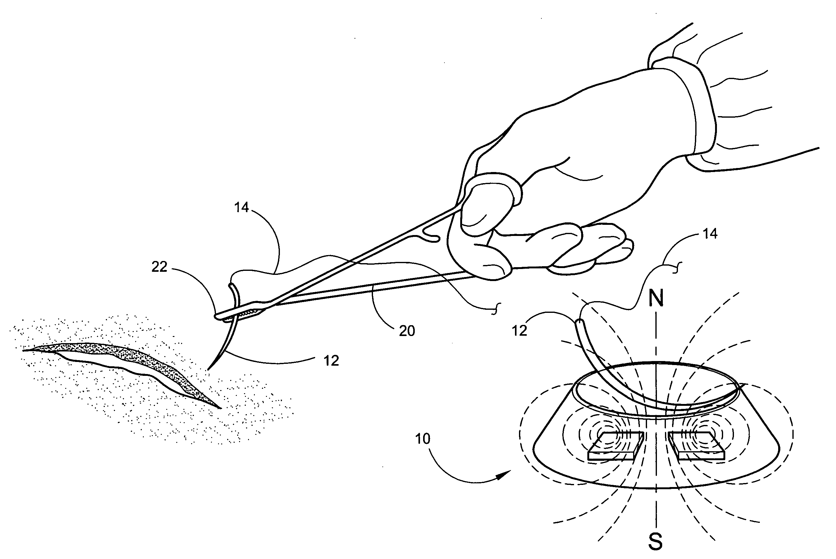
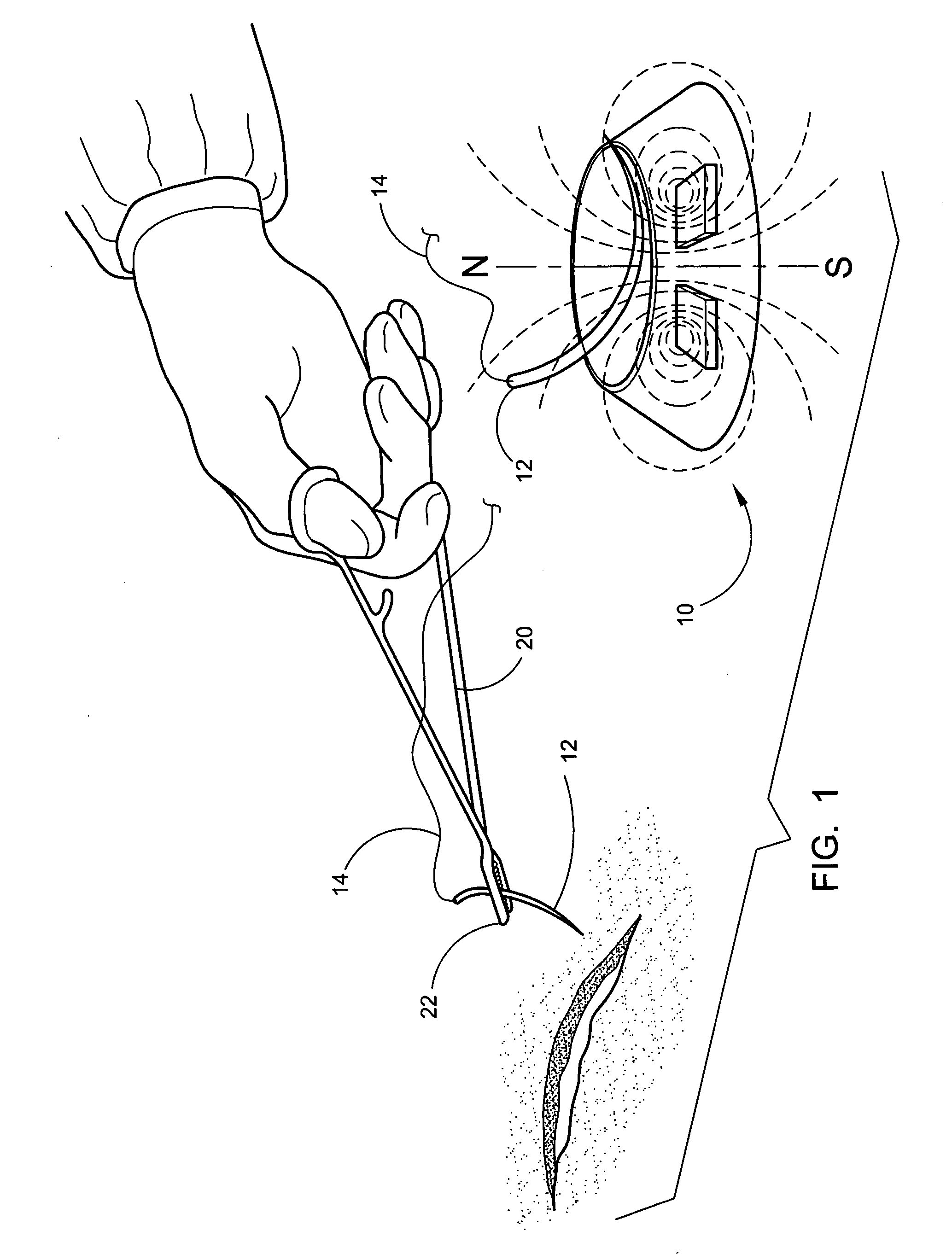
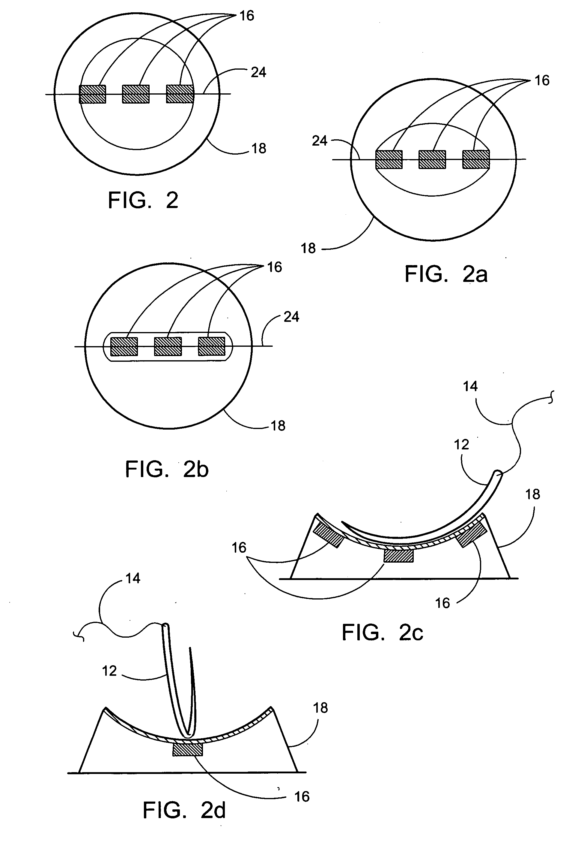
[0046] Referring now to the drawings, FIGS. 1-9 disclose some preferred embodiments of the present invention in current preferred modes. The device 10 is depicted in FIG. 1 which displays a side perspective view of a preferred embodiment of the device 10. As shown, the needle 12 is engaged with the suture or thread 14 and is being held firmly in place for use by the tension generated by pressure between the jaws of the gripping end of a needle holder 22. Also shown is the needle 12 upright on the base 18 of the device in the “ready ” position where it is held in a substantially upright position relative to the top surface 15 of the base 18 by a means for generation of a magnetic field 30 above the top surface such as permanent magnets 16. The magnets 16 project the magnetic field 30 in a fashion calculated to hold the magnetically attractive needle 12 substantially upright and in place. The magnetic fields of the device and the top surface of the base may also be employed to prefera...


PUM


Abstract

A device and method for maintaining a curved sewing needle in an upright position when the needle is deposited thereon during suturing or sewing. The device features a base with a top surface on which a curved needle may be removably deposited. Once deposited upon the top surface of the base, a magnetic field of sufficient force and vector holds the needle to a substantially vertical position wherein it is easier to grasp by a tool or fingers for the next suture. Coaxing the needle to the upright position from a sideways deposit on the top surface can be provided by a sufficient field strength and assisted by dimensioning the top surface of the base to mechanically assist the magnetic force on the deposited needle and also by employing a magnetized needle.

Description

FIELD OF THE INVENTION [0001] The present invention relates to surgical instruments used when closing an incision or wound in body tissue and to instruments in general that are used for the purpose of sewing fabric or suturing patients. In particular, the present invention relates to an instrument that magnetically assists the positioning of a needle when released from the grip of a user or surgeon. The device provides a means to pre-position the needle for easy grasping subsequent to disengagement from a tool or fingers. Likely applications include conventional surgery, minimally invasive surgical procedures such as laparoscopic and other developing image guided endoscopic techniques that are performed within the body in areas of limited access, and general sewing using a curved needle such as in upholstery or carpeting. BACKGROUND OF THE INVENTION [0002] Surgery has been long in development and the relentless advance in techniques and equipment has led to the miracles of our more ...

Claims


Application Information

Patent Timeline
IPC IPC(8): A61B17/04
CPCA61B17/06066A61B2017/00876A61B17/062
Inventor GIAP, BRANDON
Owner GIAP BRANDON
Learn More