Intervertebral implant and surgical method for spondylodesis of a lumbar vertebral column

a technology of lumbar vertebrae and implants, which is applied in the field of intervertebral implants and surgical methods for lumbar vertebrae, can solve the problems of danger of complete distraction, damage to adjacent vena cava and aorta,

Inactive Publication Date: 2007-03-08
COPF FRANZ JR
View PDF63 Cites 44 Cited by
  • Summary
  • Abstract
  • Description
  • Claims
  • Application Information

AI Technical Summary

Benefits of technology

[0030] This new method spares the patient owing to is microsurgical configuration and its application from the dorsal side, and causes only small wounds. The risk of infection is therefore considerably reduced. The patient is exposed to much less pain, and the time spent in hospital is considerably shorter.
[0032] After step b) the exposed bone fractions can be freshened, in other words superficially abraded, and this facilitates adherence with spongiosa introduced into the intervertebral space.
[0035] The method according to the invention is particularly helpful if the new intervertebral implant is used which has been described above. This implant is then screwed in with distraction, in particular of the ventral region, until the transition line between the protective elevation and the conical region of the head is at the height of the apexes in the lateral image of the ventral circumference of the vertebral bodies. With this configuration of the method according to the invention, the ventral region of the vertebral body in particular may therefore also be distracted in the required manner without risk.

Problems solved by technology

With this known intervertebral implant it is a risk to carry out a complete distraction, in particular of the ventral circumference of the vertebral body.
This is because there is some danger to damage the adjacent vena cava and the aorta.

Method used


Image

  • Intervertebral implant and surgical method for spondylodesis of a lumbar vertebral column
  • Intervertebral implant and surgical method for spondylodesis of a lumbar vertebral column
  • Intervertebral implant and surgical method for spondylodesis of a lumbar vertebral column

Examples


Embodiment Construction

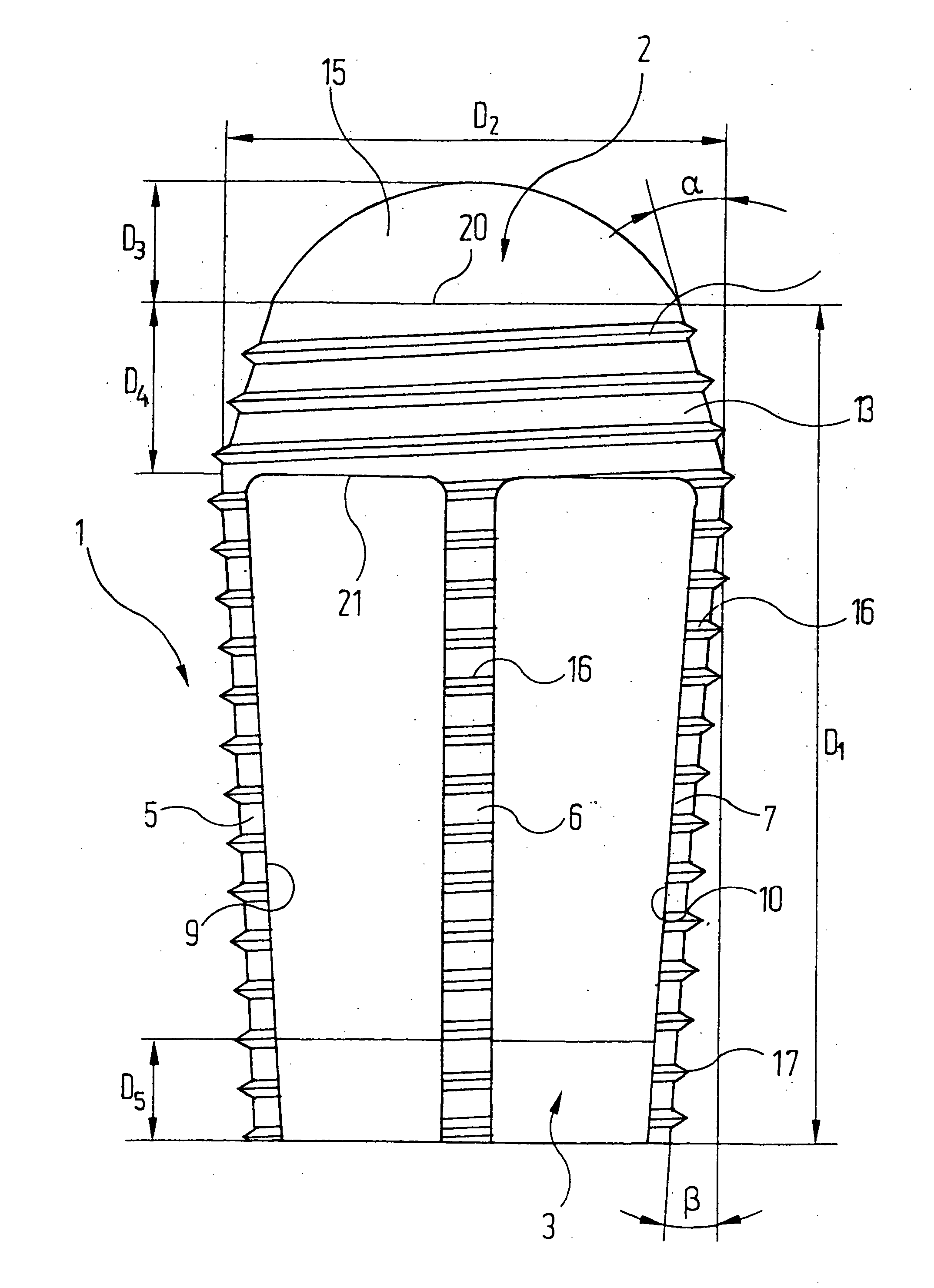
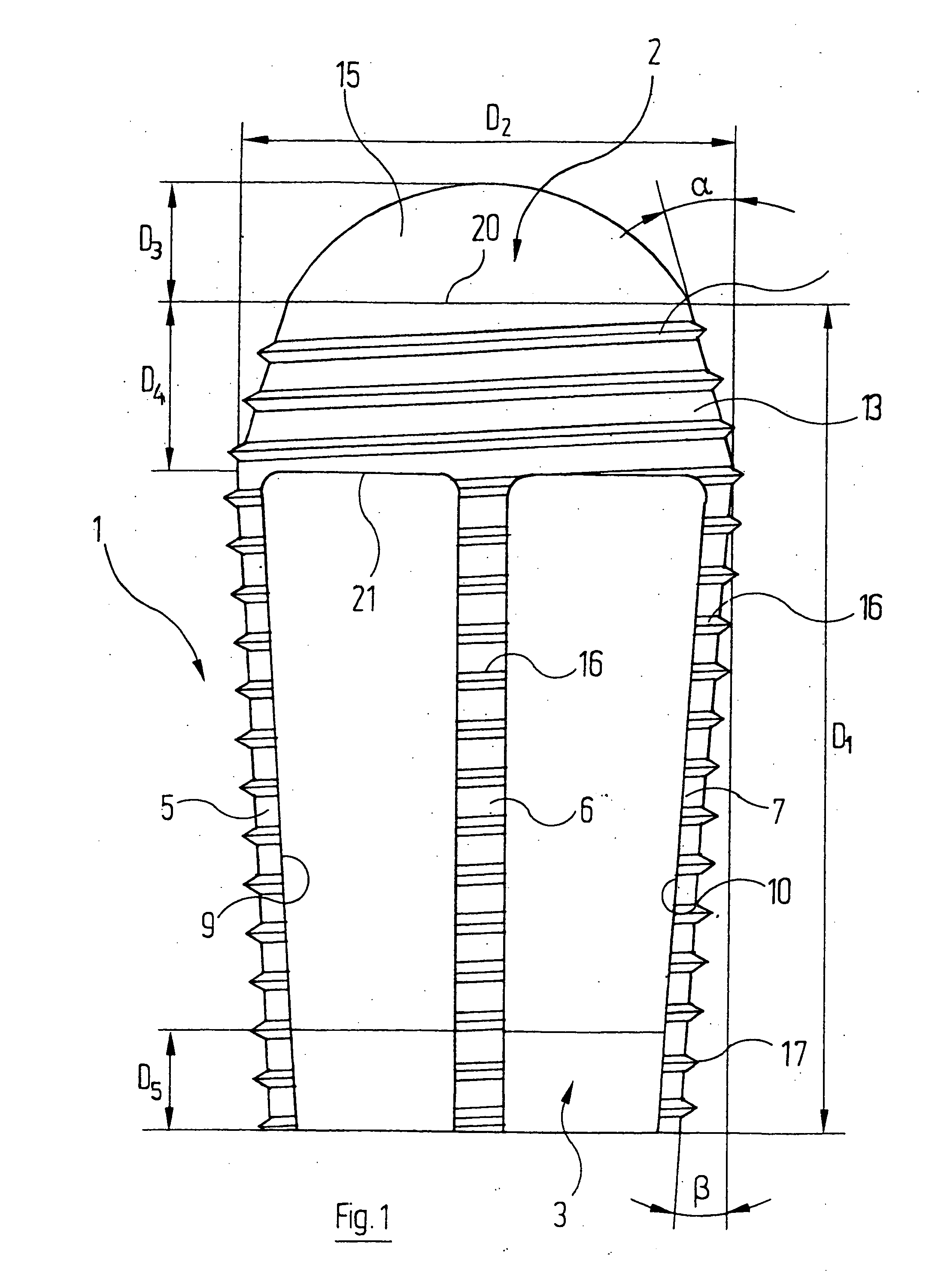
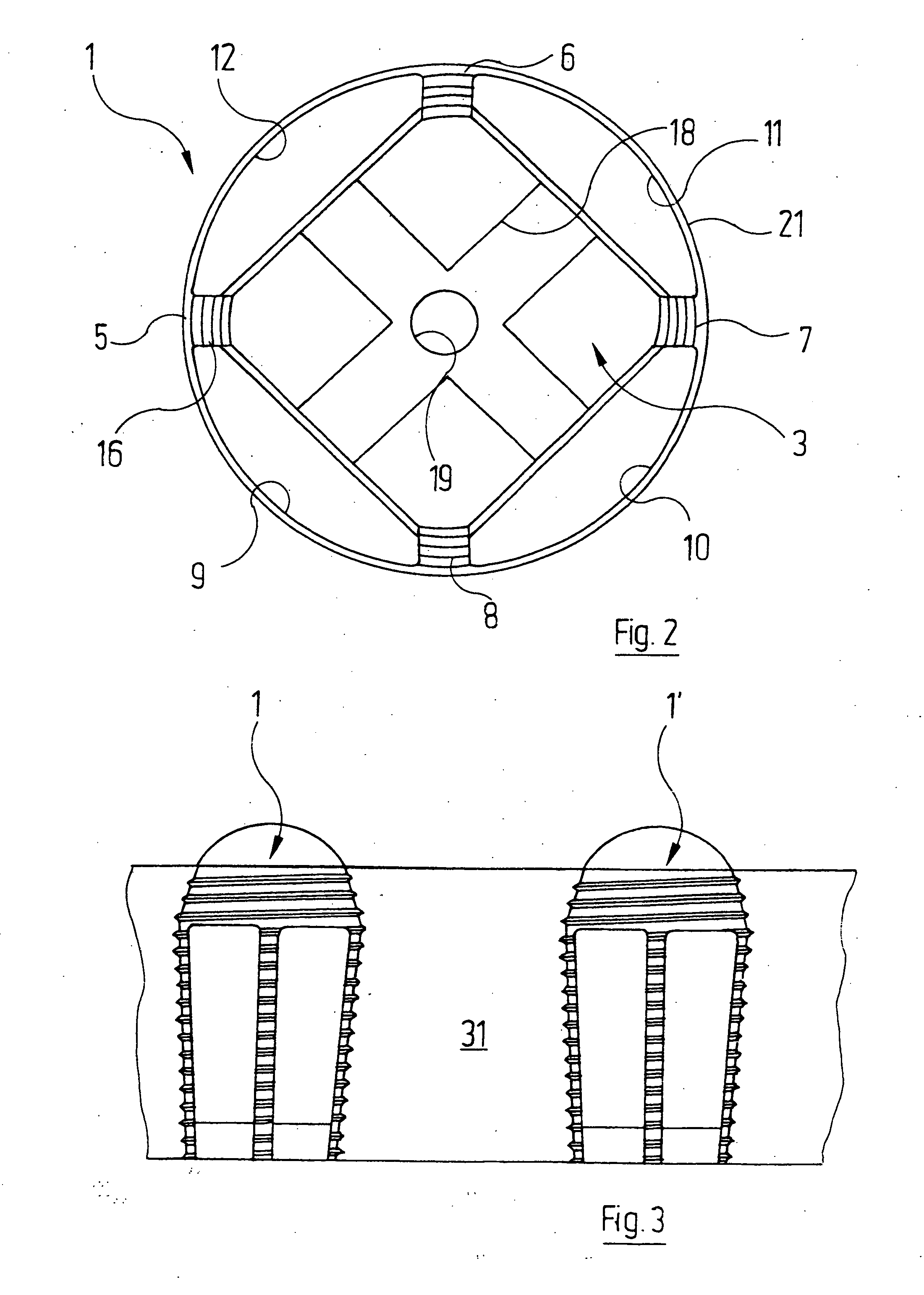
[0043] Reference will firstly be made to FIG. 1 which shows an intervertebral implant designated in its entirety by reference numeral 1. The implant comprises an (in the implanted state) ventrally-pointing head 2 and an (in the implanted state) dorsally-pointing base plate 3 which are connected to each other by four narrow struts 5, 6, 7 and 8. Large-area windows 9, 10, 11, 12 remain between the struts 5, 6, 7, 8, the head 2 and the base plate 3.

[0044] The head 2 of the intervertebral implant 1 comprises a conical portion 13, which carries an external thread 14, and a, viewed from the outside, convex protective cap 15 adjoining the conical portion 13 and forming the ventral end of the intervertebral implant 1. The protective cap 15, which has a spherical cap surface in the embodiment shown, is polished for reasons which will be elucidated below. In particular, the cap 15 does not have any sharp edges. The arrow height D3 of the protective cap 15 is at least 4 to 5 mm. The reason fo...


PUM

PropertyMeasurementUnit
angleaaaaaaaaaa
heightaaaaaaaaaa
axial length D4aaaaaaaaaa

Abstract

An intervertebral implant has a head positioned at one end of the implant. The head has a conical portion, on which an external thread is formed, and an outer end region formed by a protective elevation. The elevation is, is viewed from the outside, convexly curved and free from sharp edges. A central portion is positioned between the head and a basic structure which is formed at an opposite end of the implant. The central portion is formed by a plurality of struts extending from the head to the basic structure. The central portion is provided with an external thread and has openings formed between the head, the struts and the basic structure.

Description

CROSS-REFERENCE TO RELATED APPLICATIONS [0001] This is a continuation-in-part of International Patent Application PCT / EP2004 / 001359, which was filed on Feb. 13, 2005. The full disclosure of this earlier application is incorporated herein by reference.BACKGROUND OF THE INVENTION [0002] The invention relates to an intervertebral implant and to a method for spondylodesis of the lumbar vertebral column. [0003] German Patent No. DE 199 57 339 C2 describes an intervertebral implant comprising a head which has a conical portion with an external thread, a central portion with an external thread, and a basic structure. The central portion is formed by a plurality of struts extending from the head to the basic structure, and thus large-area windows remain open between the head, the strut and the basic structure. [0004] This known implant deliberately dispenses with the previously known sleeve-type form of intervertebral implants and instead uses a central portion with narrow struts which leav...

Claims


Application Information

Patent Timeline
Patent Type & Authority Applications(United States)
IPC IPC(8): A61F2/44A61F2/00A61F2/02A61F2/28A61F2/30A61F2/46
CPCA61F2/446A61F2310/00179A61F2002/2835A61F2002/30062A61F2002/30153A61F2002/30205A61F2002/30616A61F2002/30784A61F2002/30874A61F2002/4475A61F2210/0004A61F2230/0019A61F2230/0067A61F2310/00017A61F2310/00023A61F2310/00047A61F2/4611A61F2002/30593A61F2002/30873
Inventor COPF, FRANZ JR.PINKOWSKI, WOLFHARD
Owner COPF FRANZ JR
Why Eureka
Try Eureka