Vacuum cleaner having brush motor using deceleration rate

a vacuum cleaner and motor technology, applied in the direction of machines/engines, carpet cleaners, bowling games, etc., can solve the problems of increasing the rotation speed of the motor, increasing the number of sparks generated, and damage to the motor, so as to achieve competitive

Inactive Publication Date: 2007-03-15
SAMSUNG GWANGJU ELECTRONICS CO LTD
View PDF1 Cites 24 Cited by
  • Summary
  • Abstract
  • Description
  • Claims
  • Application Information

AI Technical Summary

Benefits of technology

[0018] Accordingly, it is an object of the present invention to provide a vacuum cleaner with a brush motor using a deceleration rate, which can produce improved suction force by rotating an impeller at a high speed and stabilizing the motor by setting the rotation speed of the impeller higher than that of the motor.
[0023] Another object of the present invention is to provide a vacuum cleaner that is competitive in terms of price by employing a low-priced brush motor that uses a deceleration rate.

Problems solved by technology

However, this causes the rotation speed of the motor to increase.
This can cause an increase in the number of sparks generated between a commutator 2 and a carbon brush 8, and may eventually damage the motor.
Generally, the reduced life span of the motor leads to a shorter life span of the vacuum cleaner.
However, the BLDC motor or the single-phase SR motor is not used widely for vacuum cleaners due to its high price.
The high price of the motor in turn leads to a high price of the vacuum cleaner, and the high price of the vacuum cleaner lowers its price competitiveness.

Method used


Image

  • Vacuum cleaner having brush motor using deceleration rate
  • Vacuum cleaner having brush motor using deceleration rate
  • Vacuum cleaner having brush motor using deceleration rate

Examples


Embodiment Construction

[0031] A brush motor of a vacuum cleaner using a deceleration rate in accordance with the first non-limiting embodiment of the present invention will now be described in detail with reference to the accompanying drawings. FIG. 4 is a schematic perspective view of a non-limiting example of a vacuum cleaner with a brush motor using a deceleration rate in accordance with the first embodiment. FIG. 5 is a schematic cross-sectional view that illustrates a non-limiting example the brush motor of the vacuum cleaner using the deceleration rate.

[0032] According to the first embodiment of the present invention, the vacuum cleaner with the brush motor using the deceleration rate may include a cleaner main body 20, a flexible hose 30, a suction brush 40, and a motor 50 positioned at the main body 20.

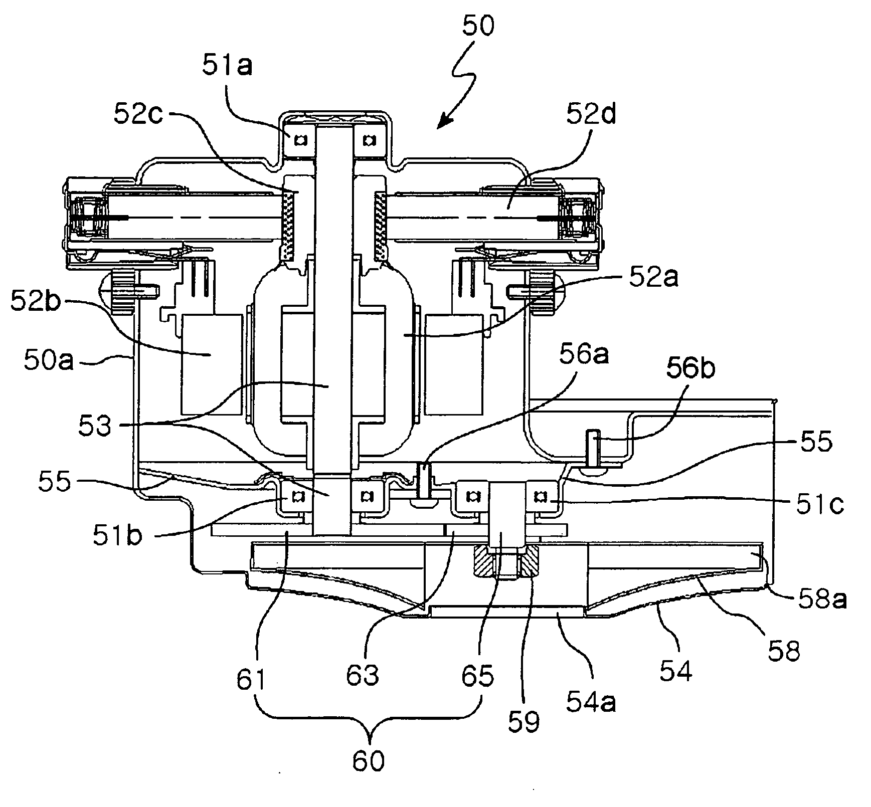
[0033] As illustrated in FIG. 5, the vacuum cleaner may include a decelerating unit 60 that connects a driving shaft 53 of the motor 50 with an impeller 58 to transfer the rotation force of the dr...


PUM


Abstract

A vacuum cleaner includes: a main body; a suction brush configured to draw particulates into the main body; a motor installed at the main body; and a decelerating unit configured to connect a driving shaft of the motor with an impeller to transfer a rotation force of the driving shaft to the impeller and to set the rotation speed of the driving shaft lower than that of the impeller.

Description

CROSS-REFERENCE TO RELATED APPLICATION [0001] This application claims the benefit of priority under 35 U.S.C. § 119 to Korean Patent Application No. 2005-84139, filed on Sep. 09, 2005, the entire contents of which are incorporated herein by reference. BACKGROUND OF THE INVENTION [0002] 1. Field of the Invention [0003] The present invention relates to a vacuum cleaner with a brush motor. More particularly, the invention relates to a vacuum cleaner with a brush motor using a deceleration rate, which can produce improved suction force by stabilizing the motor by setting the rotation speed of the impeller higher than that of the motor and rotating an impeller at a high speed. [0004] 2. Description of the Related Art [0005] In general, a vacuum cleaner uses a brush motor to generate suction force. Referring to FIG. 1, the brush motor 1 generates rotation force in an armature 4 and rotates an impeller 5 connected to a driving shaft 3 to suck dirt and air when electrical power is applied t...

Claims


Application Information

Patent Timeline
Patent Type & Authority Applications(United States)
IPC IPC(8): A47L5/12
CPCA47L5/22H02K7/116F04D25/02A47L9/28A47L9/22
Inventor LEE, MYUNG-WONYOU, JAE-SUN
Owner SAMSUNG GWANGJU ELECTRONICS CO LTD
Why Eureka
Try Eureka