Chemical trace detection portal based on the natural airflow and heat transfer of vehicles

a technology of natural airflow and vehicle heat transfer, applied in the field of vehicle thermal imaging portals, can solve the problems of inability to physically exist within the context of the concept of a “stagnant boundary layer” of explosive vapor on or near the vehicle, and the natural signal produced by the vehicle is too weak to detect, so as to achieve the effect of substantially improving the thermal imaging portal for vehicular subjects

Inactive Publication Date: 2007-03-15
FLIR DETECTION
View PDF17 Cites 20 Cited by
  • Summary
  • Abstract
  • Description
  • Claims
  • Application Information

AI Technical Summary

Benefits of technology

[0019] The following discussion is based on Applicants' understanding of the underlying theories involving the invention at this time. The subject invention is based partly on the premise that the art of explosive-detection portals for vehicular subjects may be substantially improved by taking proper account of the thermal behavior of the air surrounding the vehicle, and of the natural particulate field generated by the continuous exchange of contaminants on the vehicle surface with the environment, especially the air immediately surrounding the vehicle. As will be shown below, such consideration is central to the effective detection of concealed explosives or other substances on the vehicle. Further, active stripping, scrubbing, or other removal of trace explosives from the vehicle by mechanical means or air-jet impingement is either unnecessary, insofar as this function is automatically performed by the natural behavior of the vehicular thermal plume itself, or only becomes necessary under such circumstances that the natural signal produced by the vehicle is too weak to detect. The concept of a “stagnant boundary layer” of explosive vapor on or near the vehicle, as described in the prior art, is actually not physically possible within the context of the known behavior of the vehicular thermal plume. In contrast with the horizontal orientation of air currents in the preponderance of the prior art, the subject invention takes advantage of the natural orientation of the thermal plume of an operating vehicle, or of a vehicle which is not operating, but has been standing in a heated or sunny environment, which, as discussed below, is vertical and upward. The prior art thus introduces airflow patterns at direct variance with the natural tendency of the convective airflow about the vehicle, leading to gross inefficiencies in the collection of a concentrated sample of air from the intimate environment of the vehicle.

Problems solved by technology

Further, active stripping, scrubbing, or other removal of trace explosives from the vehicle by mechanical means or air-jet impingement is either unnecessary, insofar as this function is automatically performed by the natural behavior of the vehicular thermal plume itself, or only becomes necessary under such circumstances that the natural signal produced by the vehicle is too weak to detect.
The concept of a “stagnant boundary layer” of explosive vapor on or near the vehicle, as described in the prior art, is actually not physically possible within the context of the known behavior of the vehicular thermal plume.
The prior art thus introduces airflow patterns at direct variance with the natural tendency of the convective airflow about the vehicle, leading to gross inefficiencies in the collection of a concentrated sample of air from the intimate environment of the vehicle.

Method used


Image

  • Chemical trace detection portal based on the natural airflow and heat transfer of vehicles
  • Chemical trace detection portal based on the natural airflow and heat transfer of vehicles
  • Chemical trace detection portal based on the natural airflow and heat transfer of vehicles

Examples


Embodiment Construction

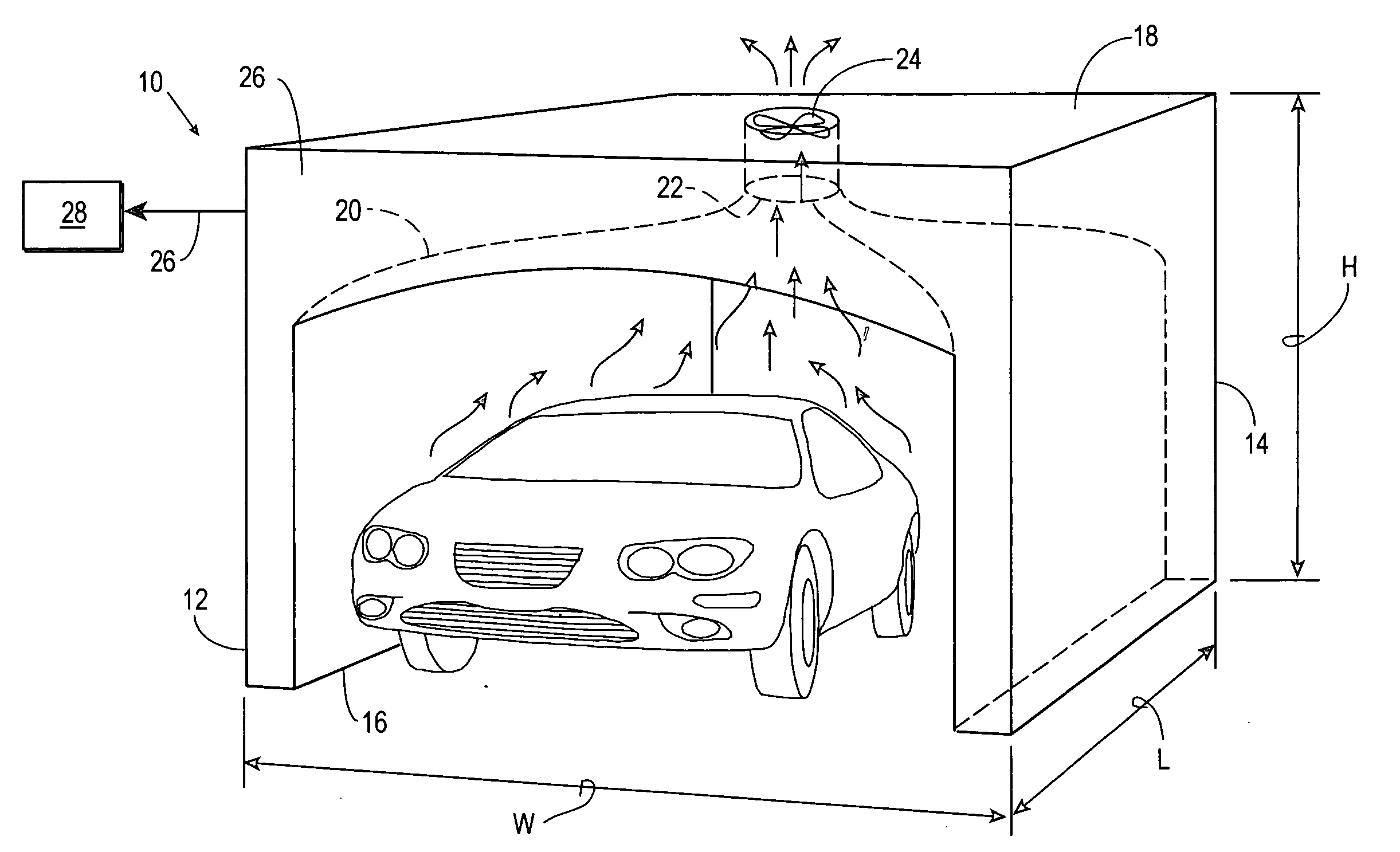
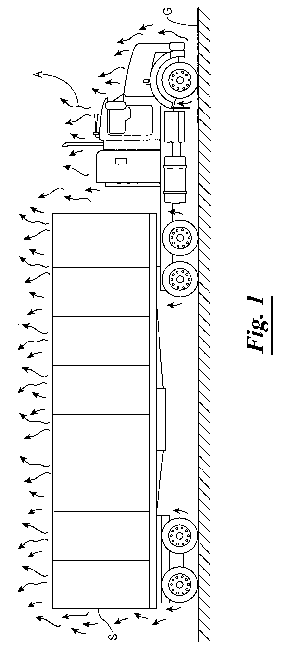
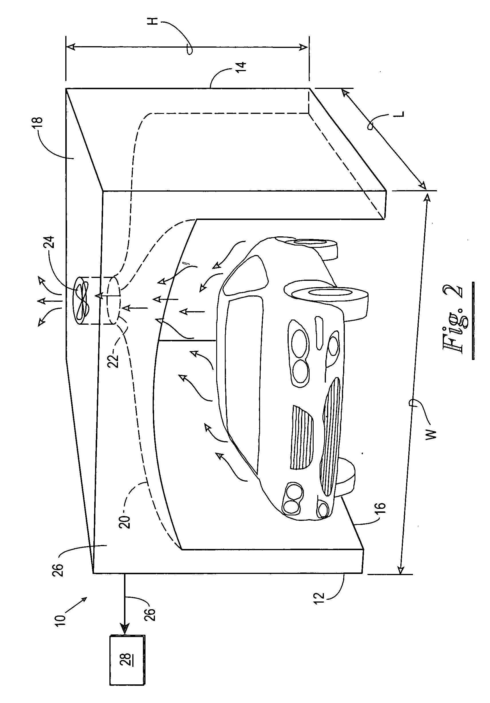
[0037] The portals of the subject invention capitalize on physical phenomena identified by the inventors herein and illustrated schematically in FIG. 1. In particular, FIG. 1 depicts a vehicular subject S standing on a substantially horizontal floor G. The vehicular subject S typically will have a temperature that exceeds the temperature of the ambient air adjacent to the vehicular subject S. The vehicular heat of the vehicular subject S will cause a warming of air adjacent to the vehicular subject S. This warmed air will effectively define a boundary layer of warm air in close proximity to the vehicular subject S. Warm air is less dense than cooler air. As a result, warm air rises relative to cooler air. This known physical phenomenon causes the warm air boundary layer adjacent the vehicular subject S to gradually flow upwardly and through the cooler air at further distances from the vehicular subject S. This upwardly flowing air is identified by arrows “A” in FIG. 1 and collective...


PUM

PropertyMeasurementUnit
speedaaaaaaaaaa
settling speedaaaaaaaaaa

Abstract

A portal is provided with a detector for detecting trace amounts of substances of interest that may be retained on the surface or interior of a vehicular subject. The portal relies upon the continuous process by which microscopic flakes of dust, dirt, pollen, and other surface and interior contaminants as well as adsorbed analyte media and analyte vapors continuously separate from the surface of vehicular subjects and escape from the interior of vehicular subjects. The portal further leverages the existence of a vehicular thermal plume consisting of a layer of warm air adjacent to the vehicular subject. The warm air rises in the cooler surrounding air and transports the microscopic flakes of surface contaminants, desorbed analyte, and analyte vapors upwardly. The portal capitalizes on this phenomenon by providing at least a partial enclosure with a funnel-shaped collector above the vehicular subject. A low speed flow of relatively dense cool air may be introduced into the portal to buoyantly lift the warmer air of the vehicular thermal plume upwardly. The air stream defined by the vehicular thermal plume and the contaminant particles, analyte media, and analyte vapors therein moves to a trap in the funnel-shaped collector above the portal. The trap cooperates with a detector for detecting the presence of molecules of interest.

Description

STATEMENT OF FEDERALLY SPONSORED RESEARCH / DEVELOPMENT [0001] Government Funding: W31P4Q-04-C-R166 DARPACROSS REFERENCE TO RELATED APPLICATIONS [0002] Not Applicable. BACKGROUND OF THE INVENTION [0003] 1. Field of the Invention [0004] The present invention relates to a portal-type sampling system for sampling the air around vehicles for purposes of detecting trace chemicals present therein. [0005] 2. Description of the Related Art [0006] The rise in worldwide terrorism has made it imperative that border traffic security stations and traffic checkpoints screen for concealed explosives as well as performing their normal function of controlling access to certain locations and searching for persons of interest. Experience has shown that concealed explosive devices have been transported onboard vehicles by terrorists on a number of occasions, some of which have resulted in disasters claiming the lives of many persons. Further, the modern terrorist is sophisticated enough to obtain and use...

Claims


Application Information

Patent Timeline
Patent Type & Authority Applications(United States)
IPC IPC(8): G01N1/08G01N1/14G01N1/40
CPCG01N1/2214G01N2001/024G01N1/24
Inventor CUMMING, COLINTOWERS, ERICPRATHER, MARK
Owner FLIR DETECTION
Why Eureka
Try Eureka