Object movement system and method

a technology of object movement and object, applied in the direction of rope railways, machine supports, train hauling devices, etc., can solve the problems of device self-propelled and heavy, device is limited in the amount of z-axis displacement that can be effected, and system fails to meet the full spectrum of ease of control, compact storage, and easy to carry

Inactive Publication Date: 2007-03-15
FORTRESS CREDIT CORP AS AGENT
View PDF7 Cites 16 Cited by
  • Summary
  • Abstract
  • Description
  • Claims
  • Application Information

AI Technical Summary

Benefits of technology

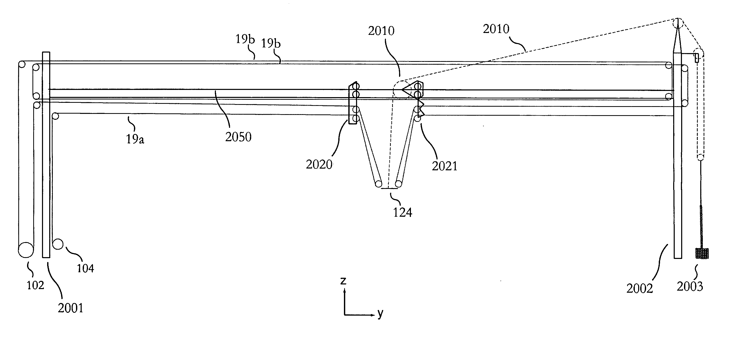
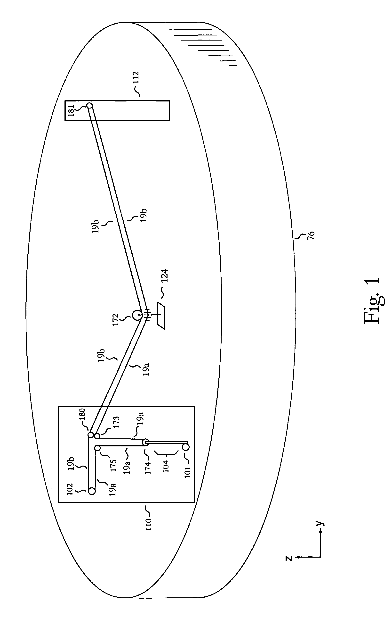
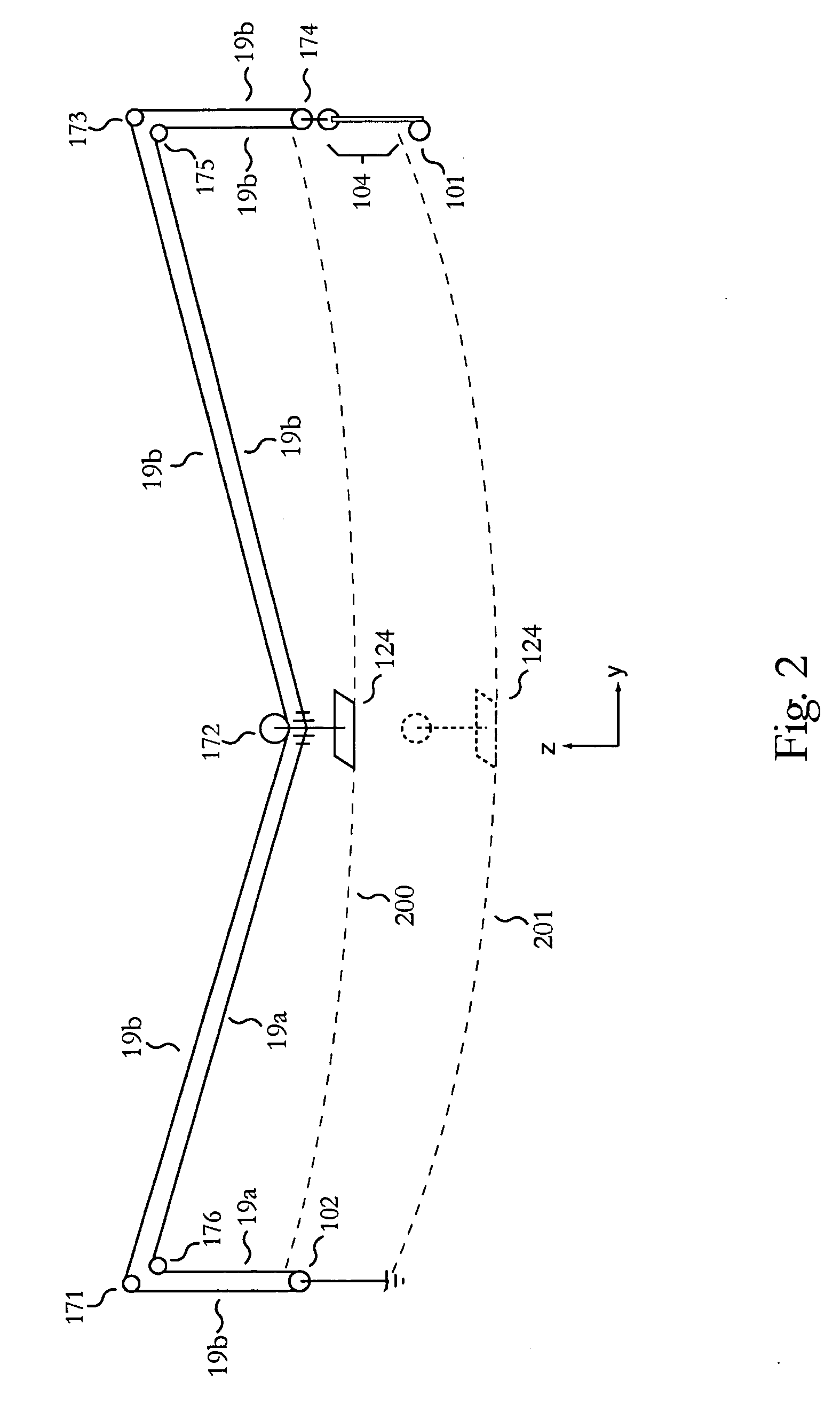
[0012] One or more embodiments of the invention are directed to a mounting system configured to move objects throughout two-dimensional and three-dimensional space by using at least one line (e.g., rope, cable or other mechanism) that is optionally reeved about a mounting beam and coupled with both opposing sides of a platform either rotationally or fixedly and wherein the platform may comprise the object to be moved. One line, which may be coupled with the optional mounting beam, controls both the Y-axis motion and Z-axis motion of the platform and is designated the YZ movement line. A nested embodiment of the invention may comprise a second line or a portion of the first line that is mounted parallel or non-parallel with...

Problems solved by technology

These systems fail to satisfactorily achieve the full spectrum of ease of control, compact storage, ease of transport, speed, load bearing, extensibility, maintainability and platform stability.
The device is self propelled and is heavy.
The device is limited in the amount of Z-axis displacement that can be effected.
The balloons may be raised or lowered but are cumbersome in enclosed environments and stadiums where they w...

Method used


Image

  • Object movement system and method
  • Object movement system and method
  • Object movement system and method

Examples


Embodiment Construction

[0047] Embodiments of the invention are directed to a Mounting System Reeved to Move an Object in Two-Dimensions and Methods Relating to Same. In the following description numerous specific details are set forth in order to provide a more thorough understanding of embodiments of the invention. It will be apparent, however, to an artisan of ordinary skill that the present invention may be practiced without incorporating all aspects of the specific details described herein. Any mathematical references made herein are approximations that can in some instances be varied to any degree that enables the invention to accomplish the function for which it is designed. In other instances, specific features, quantities, or measurements well-known to those of ordinary skill in the art have not been described in detail so as not to obscure the invention. Readers should note that although examples of the invention are set forth herein, the claims, and the full scope of any equivalents, are what de...


PUM


Abstract

Moves objects through two/three dimensional space via at least one movement line coupled with opposing sides of a platform. The movement line(s) control the horizontal and vertical (Z-axis) motion of the platform. Displacing a portion of the movement line(s) allows vertical displacement of the platform. There is no need for complex computer control since Z-axis displacement is substantially independent of horizontal movement. Nested embodiments utilizing one or more line allow for three-dimensional movement of an object or angular displacement of the platform with respect to the vertical axis. A mounting beam for positioning and supporting the Z-axis and horizontal axis motors may also be positioned independently of the platform. Many useful devices may be attached to the platform. Some embodiments may utilize two lines to provide redundancy and some of these embodiments may only drive one of the two lines for Y axis movement.

Description

[0001] This application is a continuation in part of U.S. patent application Ser. No. 10 / 906,621, filed Feb. 27, 2005 entitled “Object Movement System and Method” the specification of which is hereby incorporated herein by reference, which is a continuation in part of Patent Cooperation Treaty Application PCT / US2004 / 035092, filed Oct. 25, 2004 entitled “A Mounting System Reeved to Move an Object in Two-Dimensions and Methods Relating to Same” the specification of which is hereby incorporated herein by reference which is a continuation in part of U.S. patent application Ser. No. 10 / 709,918, filed Jun. 4, 2004 entitled “A Mounting System Reeved to Move an Object in 2-D and Methods Relating to Same” the specification of which is hereby incorporated herein by reference, which is a continuation in part of U.S. patent application Ser. No. 10 / 605,778, filed Oct. 25, 2003 entitled “System and Method for Moving Objects within Two-Dimensional Space” the specification of which is hereby incorp...

Claims


Application Information

Patent Timeline
IPC IPC(8): B61B9/00
CPCB61B7/02F16M11/42F16M11/425F16M11/18F16M11/046
Inventor RODNUNSKY, JIM
Owner FORTRESS CREDIT CORP AS AGENT
Why Eureka
Try Eureka