Electrical conductor element

a technology of electrical conductors and elements, applied in the direction of electrical equipment, coatings, applications, etc., can solve the problems of metalised strips and the adhesive connection to the conductive fabric layer to wear, and reduce the accuracy of the position determination of mechanical interactions

Inactive Publication Date: 2007-03-15
PERATECH
View PDF4 Cites 11 Cited by
  • Summary
  • Abstract
  • Description
  • Claims
  • Application Information

AI Technical Summary

Benefits of technology

[0012]FIG. 3 shows illustrates an arrangement of electrical

Problems solved by technology

A problem with using a metallised strip of conductive fabric for the conductive elements of a flexible position sensor is that the use, and flexing and bending of the position sensor causes the metallised strips and the adhesive connection to the con

Method used


Image

  • Electrical conductor element
  • Electrical conductor element
  • Electrical conductor element

Examples


Embodiment Construction
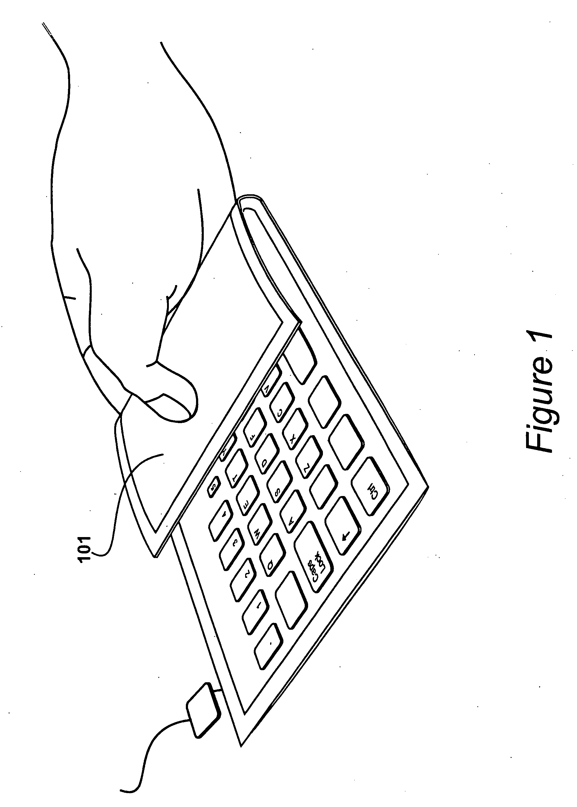
FIG. 1

[0017] A flexible position sensor is shown in FIG. 1. Portable sensor 101 is a peripheral data input device, in the form of an alphanumeric keyboard, for a mobile telephone or other electronic processing device. The portable sensor 101 is flexible to allow it to be folded for convenient transportation and storage. The sensor 101 is therefore required to withstand repeated bending and folding operations to provide a working life of satisfactory length.
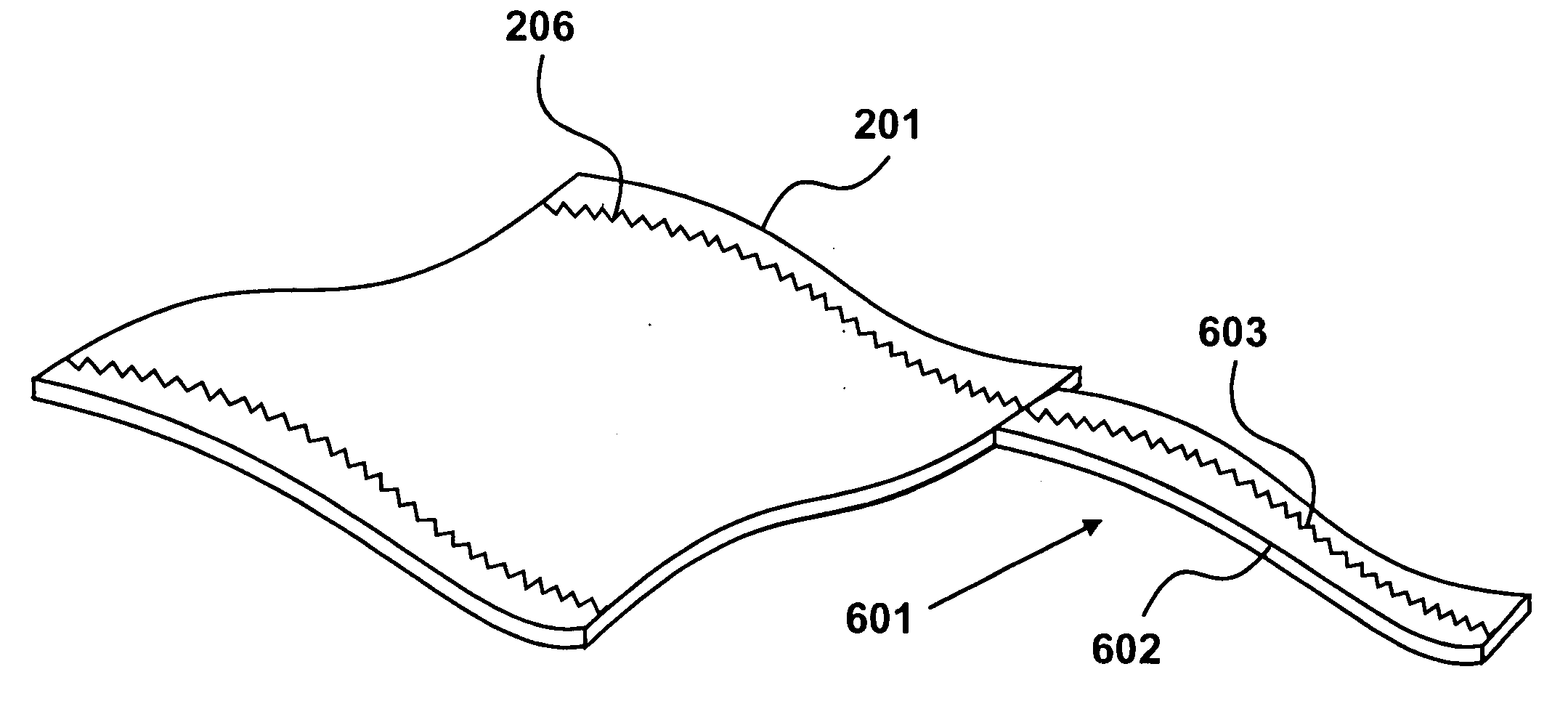
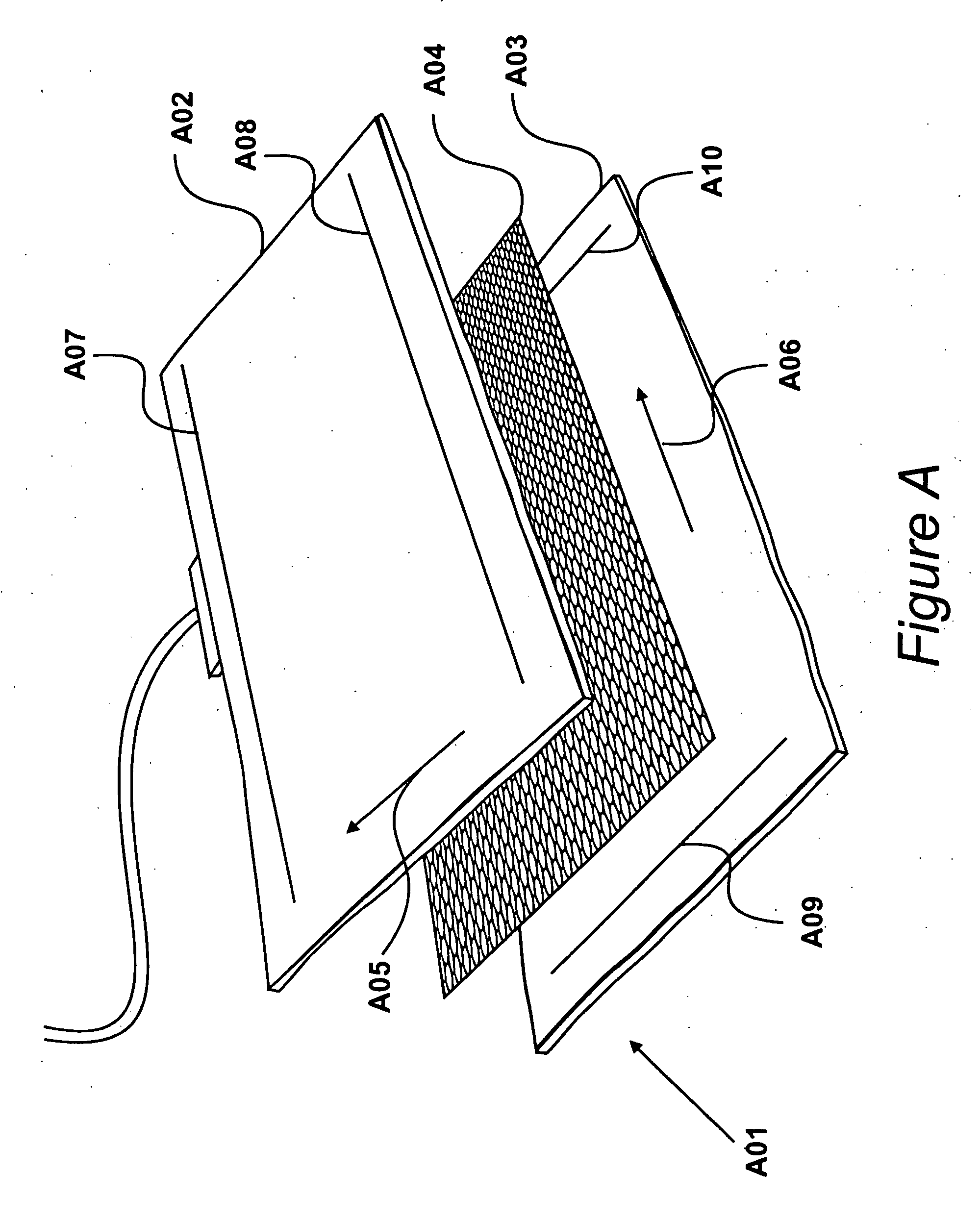
FIG. 2

[0018] Flexible layers of sensor 101 are shown in FIG. 2. The sensor 101 utilises a first conductive fabric layer 201, a second conductive fabric layer 202 and an intermediate separating layer 203 disposed between the first conductive fabric layer 201 and the second conductive fabric layer 202. The intermediate separating layer 203 is configured to separate the first conductive fabric layer 201 and the second conductive fabric layer 202 in the absence of a mechanical interaction with the position sensor 101. The intermediat...


PUM

PropertyMeasurementUnit
Lengthaaaaaaaaaa
Pressureaaaaaaaaaa
Electrical conductivityaaaaaaaaaa

Abstract

A position sensor is shown for detecting the position of a mechanical interaction. The sensor includes a first conductive fabric layer having electrically conductive fibres incorporated therein to allow conduction in a first direction. The first conductive fabric layer has a first electrical conductor element a and a second electrical conductor element positioned at opposite ends of a first conductive path extending in a first direction. The first and second electrical conductor elements each comprise a length of electrically conductive thread machined to form a conductive track of stitches that extends in a second direction substantially perpendicular to the first direction. The first and second electrical conductor elements do not intersect.

Description

CROSS REFERENCE TO RELATED APPLICATION [0001] This application claims priority from United Kingdom Patent Application No. 0518371.0, filed 09 Sep. 2005, the entire disclosure of which is incorporated herein by reference in its entirety. FIELD OF THE INVENTION [0002] The present invention relates to an electrical conductor element, in particular to a flexible electrically conductive fabric conductor element for making electrical connection to a flexible conductive fabric sensor. DESCRIPTION OF THE RELATED ART [0003] Figure A shows layers of a flexible position sensor A01 having a first conductive fabric layer A02, a second conductive fabric layer A03 and an intermediate separating layer A04 disposed between the first conductive fabric layer A02 and the second conductive fabric layer A03. The intermediate separating layer A04 is configured to separate the first conductive fabric layer A02 and the second conductive fabric layer A03 in the absence of a mechanical interaction with the po...

Claims


Application Information

Patent Timeline
IPC IPC(8): B32B7/08D05C17/00B32B5/26B32B7/025B32B7/03G06F3/02G06F3/041H01H3/14H01H13/702
CPCB32B5/02G06F2203/04102B32B5/26B32B7/02B32B2250/20B32B2255/02B32B2255/205B32B2255/24B32B2262/0261B32B2307/202B32B2307/206B32B2307/546B32B2457/00B32B2457/08G06F3/0221G06F3/0414H01H3/141H01H13/702H01H2003/143H01H2203/01H01H2223/052B32B5/08B32B7/025B32B7/03H01H13/52H01H13/704
Inventor BURKITT, JOHNWALKINGTON, STUART MARK
Owner PERATECH
Why Eureka
Try Eureka