Energy Channeling Sun Shade System and Apparatus

a technology of energy channeling sun shade and solar energy, applied in the direction of solar heat collectors for particular environments, solar radiation concentration, moving/orienting solar heat collectors, etc., can solve the problems of difficult management of solar glare, difficult to control climate control and lighting, and only useful for new construction passive solar design. , to achieve the effect of increasing the solar flux

Inactive Publication Date: 2007-03-15
STRAKA CHRISTOPHER W
View PDF99 Cites 45 Cited by
  • Summary
  • Abstract
  • Description
  • Claims
  • Application Information

AI Technical Summary

Benefits of technology

[0017] The heat dissipating conduits of the louvers are manifolded together in the shading system module that is connected to a building's Heating / Ventilation / AC (HVAC) systems. The heat produced as a waste byproduct of the PV cell operation is thus channeled for productive use. The heat channeled from the shading system modules reduces the amount of conventional energy required by the building thereby offsetting conventional energy costs. This energy savings is in addition to the electricity savings realized by not having to purchase from the utility grid since the PV cells on the louvers produce useable electricity. When the building is connected to the grid to supply electricity, the surplus produced by the shading modules turns the building's electric meter backwards and earns credits toward electricity consumed from the grid when the building's demand exceeds supply.
[0019] Modules may also be stationary and constructed with reflective material that redirects solar gain from a building onto stationary solar receivers. The reflective material sits in the foreground of a module in the space that is otherwise allowed for shadowing between rows of solar receivers mounted on a building surface, preferably a flat roof. The modules are oriented along an east-west axis. As the sun's altitude changes throughout a year, the southerly reflective surfaces in the “foreground” consistently reflect the sun's incident rays to energy channeling solar receivers on the north edge of the module. The effect is to avoid solar gain on the building surface, preferably the roof, and to increase the solar flux striking the solar receivers having the effect of concentration.

Problems solved by technology

Solar energy gain in buildings creates climate control and lighting problems due to heat gain and lighting glare, respectively.
However, passive solar design usually involves large south facing windows and it is difficult to manage solar glare while optimizing heat gain that is absorbed indiscriminately.
Also, passive solar design is only useful for new construction, as it must be incorporated into the basic architecture.
Traditional shading systems that completely or partially block solar energy including awnings, draperies, shutters, or landscaping may help limit the amount of energy absorbed by the building, but do nothing to capture the energy for useful purposes.
Integration with a building structure is a challenge due to live and dead loads created by wind and point loading when using load-bearing mounting poles at the interface to the mounting surface.
Although PV electricity production is mentioned in U.S. Pat. No. 4,020,827, the curved geometry of the reflector surface would created non-uniform angles of the reflected rays.
As a result there would be no effective power increase from the apparent concentration since crystalline silicon (c-si) PV requires uniformity of direct beam sunlight to increase current.

Method used


Image

  • Energy Channeling Sun Shade System and Apparatus
  • Energy Channeling Sun Shade System and Apparatus
  • Energy Channeling Sun Shade System and Apparatus

Examples


Embodiment Construction

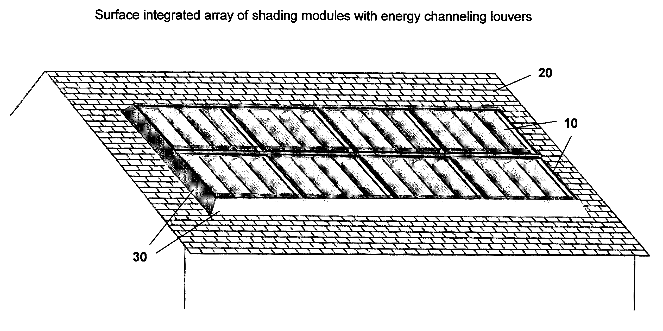
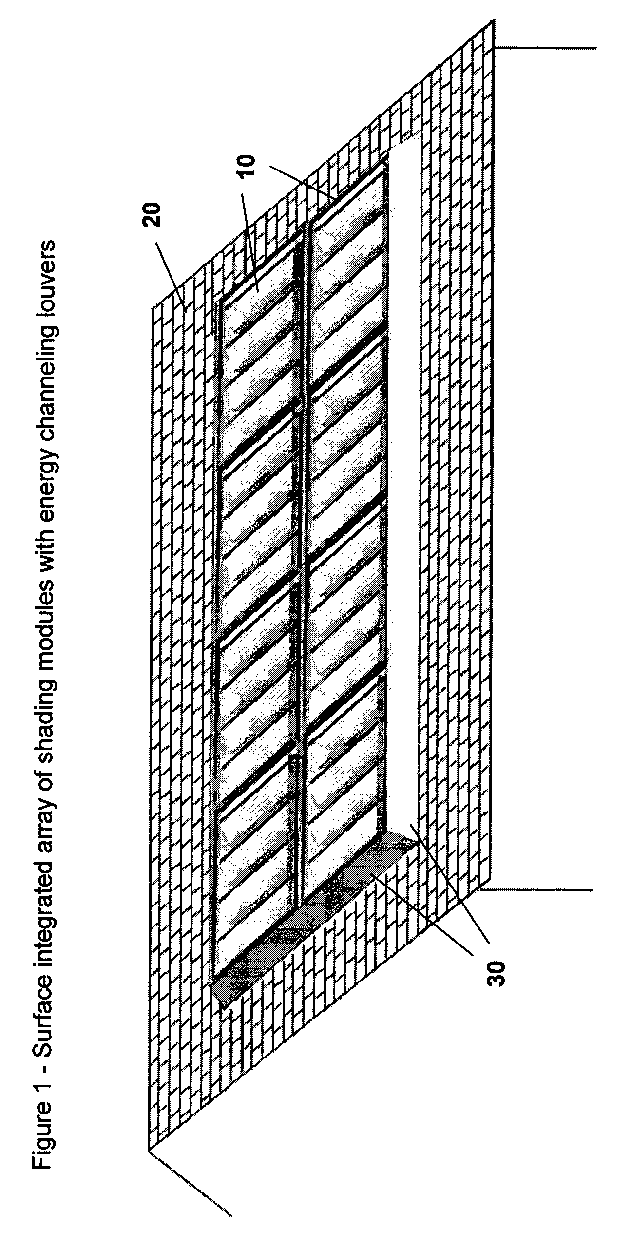
[0035]FIG. 1 shows multiple modules 10 of a shading system affixed to a sloped roof 20. An optional flashing 30 is also shown for purposes of cladding and integrating with the roof plenum. The flashing is depicted as an angled housing attached to sides of the entire shading system.

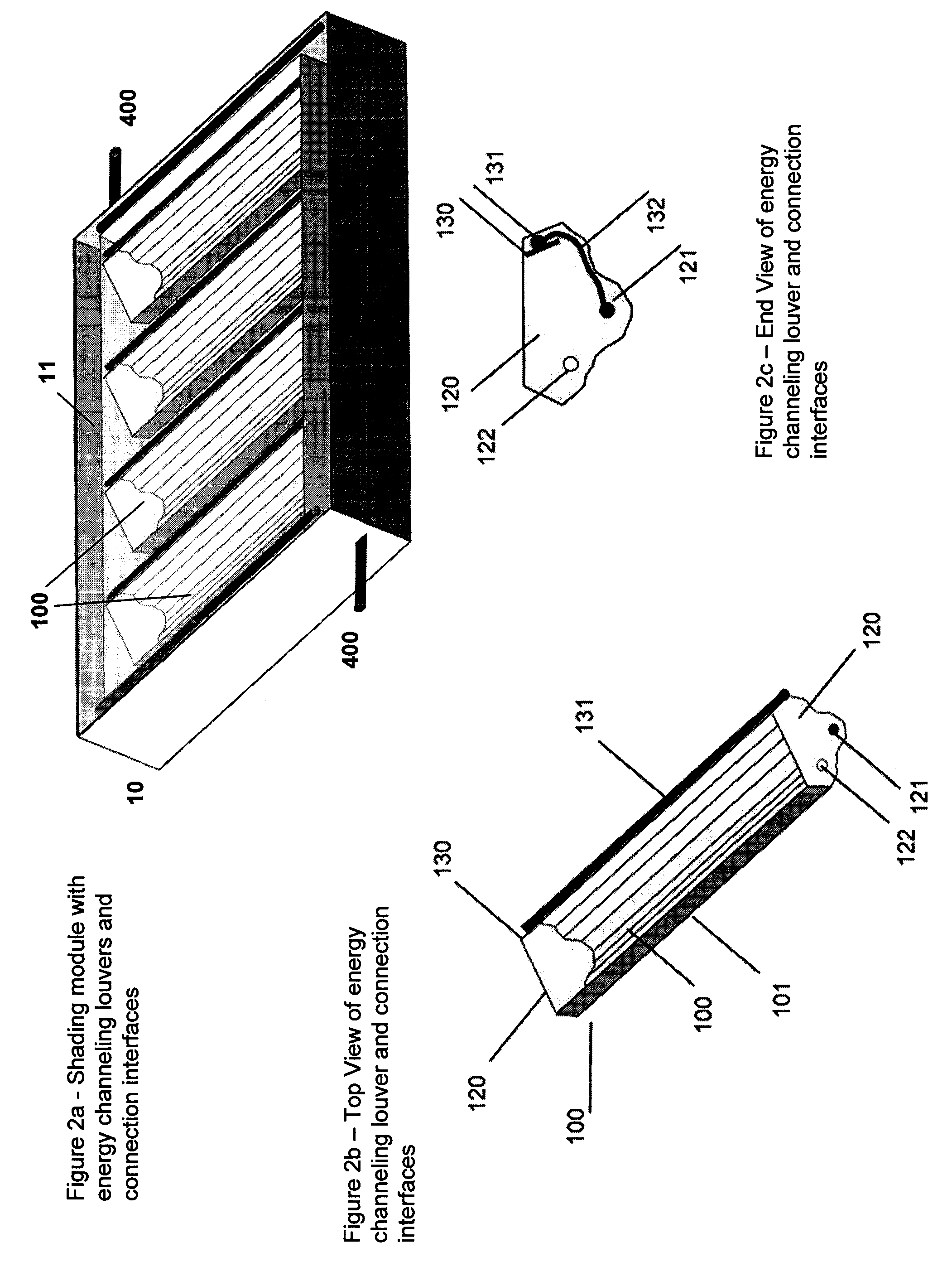
[0036]FIG. 2a shows details of one type of module 10 that may be used in the shading system invention. The module is covered with a transparent or translucent glazing 11 that protects the contents of the module and provides a weather tight seal especially when the system is integrated with the roof plenum. In this embodiment, energy channeling louvers 100 intercept solar energy thereby shading the building from uncontrolled solar gain. The energy channeling louvers are connected in a header-riser arrangement to parallel tubing that carries an antifreeze solution via a manifold 400 that integrate with a building's hot water, heating, or cooling system when used with an absorption chiller that converts heat...


PUM


Abstract

An invention is disclosed that shades a building from solar energy gain while simultaneously channeling intercepted energy in the form of heat and electricity for useful purposes. The invention is mounted optimally on exterior building surfaces having some direct exposure to the sun. The invention may be installed on the building surface so that it integrates with the building envelope to provide cladding against the weather in addition to shade. The invention includes modular units, each having several louvers that track the movement of the sun to provide optimal shading, and optionally, lighting when the module is implemented as a skylight to allow daylight to pass through into the building interior. Each louver contains photovoltaic cells, a heat dissipating substrate to which photovoltaic cells are mounted, and an optional concentrator lens and / or reflector used to channel solar energy using inexpensive materials. Alternatively, the invention includes of stationary, modular units with reflective surfaces on the foreground that channel solar energy onto fixed solar receivers in the background. The effect is to avoid solar gain to the building surface and to concentrate solar flux onto solar receivers.

Description

CROSS REFERENCE TO RELATED APPLICATION [0001] The present application claims the priority benefit of U.S. provisional patent application Ser. No. 60 / 715,555, filed Sep. 9, 2005, of the same title by the same named inventor. The entire contents of that prior application are incorporated herein by reference.BACKGROUND OF THE INVENTION [0002] 1. Field of the Invention [0003] The present invention relates to energy saving. More particularly, the present invention relates to solar energy systems. Still more particularly, the present invention relates to systems and methods to enhance the effectiveness of solar energy gain through shade impact improvements. [0004] 2. Description of the Prior Art [0005] Solar energy gain in buildings creates climate control and lighting problems due to heat gain and lighting glare, respectively. Most approaches to managing solar energy gain are characterized by blocking or reflecting the continuum of infrared and visible spectra away from the building usin...

Claims


Application Information

Patent Timeline
Patent Type & Authority Applications(United States)
IPC IPC(8): F24J2/46
CPCE04D13/033H01L31/0547E06B2009/2476F24J2/045F24J2/07F24J2/14F24J2/54Y02B10/20Y02E10/41Y02E10/44Y02E10/45Y02E10/47Y02E10/52Y02B10/10E06B9/386F24S20/67F24S23/74F24S20/20F24S30/40Y02E10/40
Inventor STRAKA, CHRISTOPHER W.
Owner STRAKA CHRISTOPHER W
Why Eureka
Try Eureka