Network device, device link system, and device link method
Inactive Publication Date: 2007-03-15
FUJIFILM BUSINESS INNOVATION CORP
View PDF7 Cites 13 Cited by
Summary
Abstract
Description
Claims
Application Information
AI Technical Summary
This helps you quickly interpret patents by identifying the three key elements:
Problems solved by technology
Method used
Benefits of technology
[0009] With the above configuration, the user is allowed to use the device comfortably without being obliged to do a troublesome wo
Problems solved by technology
This means that the user is obliged to do a troublesome wo
Method used
Image
Click on the blue label to locate the original text in one second.
Reading with bidirectional positioning of images and text.
Examples
first embodiment
[First Embodiment]
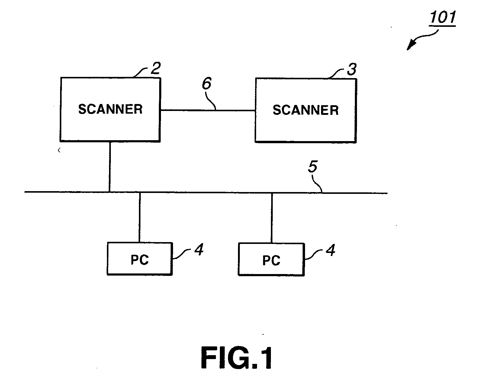
[0022]FIG. 1 shows a system configuration for a device link system 101 according to a first embodiment of the present invention.
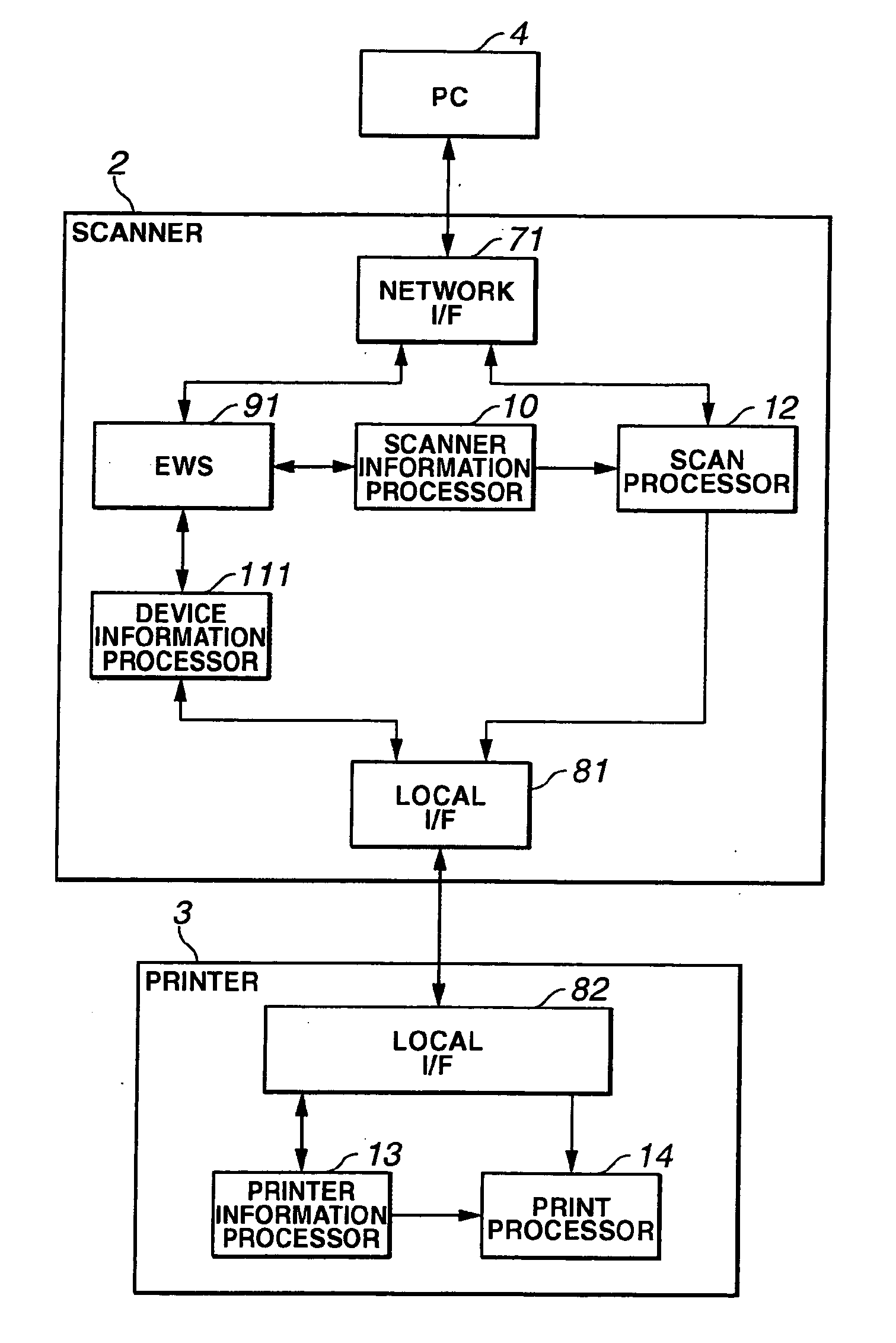
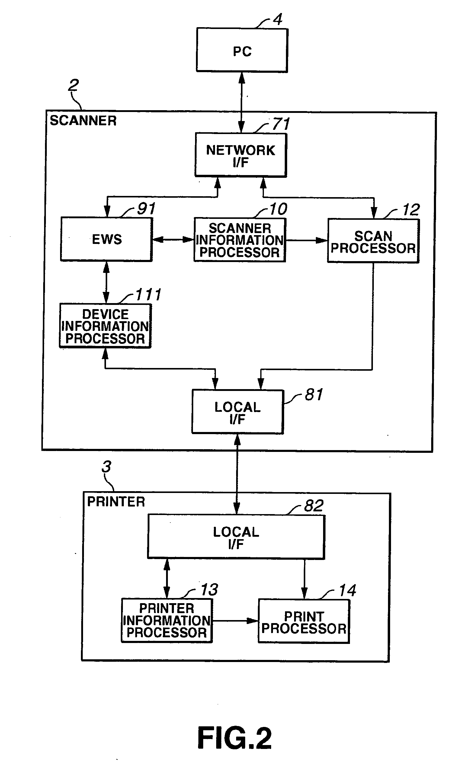
[0023] As shown in FIG. 1, the device link system 101 includes a scanner 2, a printer 3, and plural PCs 4, that are the devices according to the present invention. The scanner 2 and the PCs 4 are connected to a network 5. Further, the scanner 2 and the PCs 4 are P2P connected to each other through a USB (Universal Serial Bus) cable 6.
[0024] The system as shown in FIG. 1 is called a scanner-printer system, in which the scanner 2 and the printer 3 are coupled with a loose coupling interface such as a USB interface in terms of both software and hardware. In this scanner-printer system, the printer 3 is not provided with any special software or hardware exclusively for connecting the scanner 2, so that the printer 3 can be provided to users at a moderate price.
[0025] The scanner 2 performs scan processing to scan an original document to gen...
second embodiment
[Second Embodiment]
[0059]FIG. 5 shows a system configuration for a device link system 102 according to a second embodiment of the present invention.
[0060] As shown in FIG. 5, the device link system 102 includes a scanner 2, a printer 3, and PCs 4, which are the devices according to the present invention, and the scanner, the printer, and the PCs are connected through a network. The scanner and the printer are P2P (Peer to Peer) connected to each other via a USB (Universal Serial Bus) cable 6.
[0061] Specifically, the scanner 2 and the printer 3 are network connected through an Ethernet (registered trademark) cable or the like, and are also locally connected through a USB cable or the like.
[0062] The system as shown in FIG. 5 is called a scanner-printer system, in which the scanner 2 and the printer 3 are coupled with a loose coupling interface such as a USB interface in terms of both software and hardware. In this scanner-printer system, the printer 3 is not provided with any spec...
PUM
Abstract
In a device link system for connecting a first device and a second device through a communication interface, the first device comprises a network connection unit that connects the first device to a network; a web server that delivers a web page describing first device information relating to the first device via the network connection unit; an acquisition unit that acquires second device information relating to the second device from the second device via the communication interface; and a web page processor that generates a page describing the second device information acquired by the acquisition unit and adds the generated page to the web page, and the second device comprises a provision unit that provides the second device information to the first device via the communication interface upon receiving a request for the second device information from the first device.
Description
BACKGROUND OF THE INVENTION [0001] 1. Field of the Invention [0002] The present invention relates to a device, a device link system, and a device link method, and more particularly to a device, a device link system, and a device link method utilizing an EWS (Embedded Web Server) function. [0003] 2. Description of the Related Art [0004] Conventionally, there have been known information processing systems and methods which are able to realize a network copying function to read an image by means of a scanner connected to the network and to cause an arbitrarily desired printer to print out the image, with simple operations similar to operations for an all-in-one type copying machine (see Japanese Patent Application Publication No. 2000-47771, for example). [0005] Recent developments in technology have incorporated an EWS function into network devices such as scanners and printers. As a result, a user can access the EWS of such device by entering an IP address of the device as a URL into...
Claims
Application Information
Patent Timeline
Application Date:The date an application was filed.
Publication Date:The date a patent or application was officially published.
First Publication Date:The earliest publication date of a patent with the same application number.
Issue Date:Publication date of the patent grant document.
PCT Entry Date:The Entry date of PCT National Phase.
Estimated Expiry Date:The statutory expiry date of a patent right according to the Patent Law, and it is the longest term of protection that the patent right can achieve without the termination of the patent right due to other reasons(Term extension factor has been taken into account ).
Invalid Date:Actual expiry date is based on effective date or publication date of legal transaction data of invalid patent.