Tensioned scanner rails

a scanner rail and tensioning technology, applied in the field of tensioning scanner rails, can solve the problems of inability to accurately represent sheet material produced, inability to test, and large guide rails, etc., and achieve the effects of high damping, high natural frequency, and inability to accurately represent sheet material

Active Publication Date: 2007-03-15
HONEYWELL INT INC
View PDF10 Cites 22 Cited by
  • Summary
  • Abstract
  • Description
  • Claims
  • Application Information

AI Technical Summary

Benefits of technology

[0020] The tension rods are inherently flexible elongated guides that are made, for instance, from parallel lay rope, pultrusion or other high specific tensile strength material under high tension to provide a straight path for a lightweight sensor to travel on. Such a design has a number of advantages including: inherent insensitivity to thermal distortion, high natural frequencies, high damping, naturally straight design for low manufacturing cost, and compact cross section.

Problems solved by technology

Although various properties of sheet materials can be detected by off-line laboratory testing, such tests often are not practical because of the time required for sample acquisition and analysis.
Also, laboratory testing has the shortcoming that samples obtained for testing may not accurately represent sheet material that has been produced.
The guide members often are quite massive.
However, this is often very difficult because of space restrictions in a facility.
To generate the required inertia levels, however, the dimensions of the guide members often become so large that they cannot fit within the space allotted.
While sag can be compensated for with manufacturing methods, long and bulky, low inertia, guide members are still susceptible to resonant vibration deflection.
Thermal distortion of the structures caused by uneven heating often times must be dealt with no matter how strongly the guide members are built.

Method used


Image

  • Tensioned scanner rails
  • Tensioned scanner rails
  • Tensioned scanner rails

Examples


Embodiment Construction

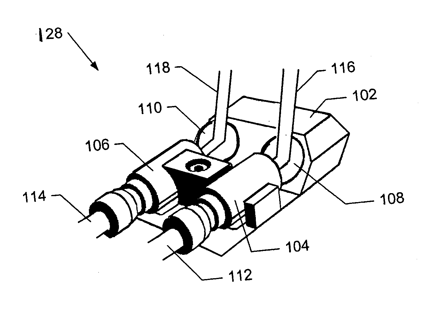
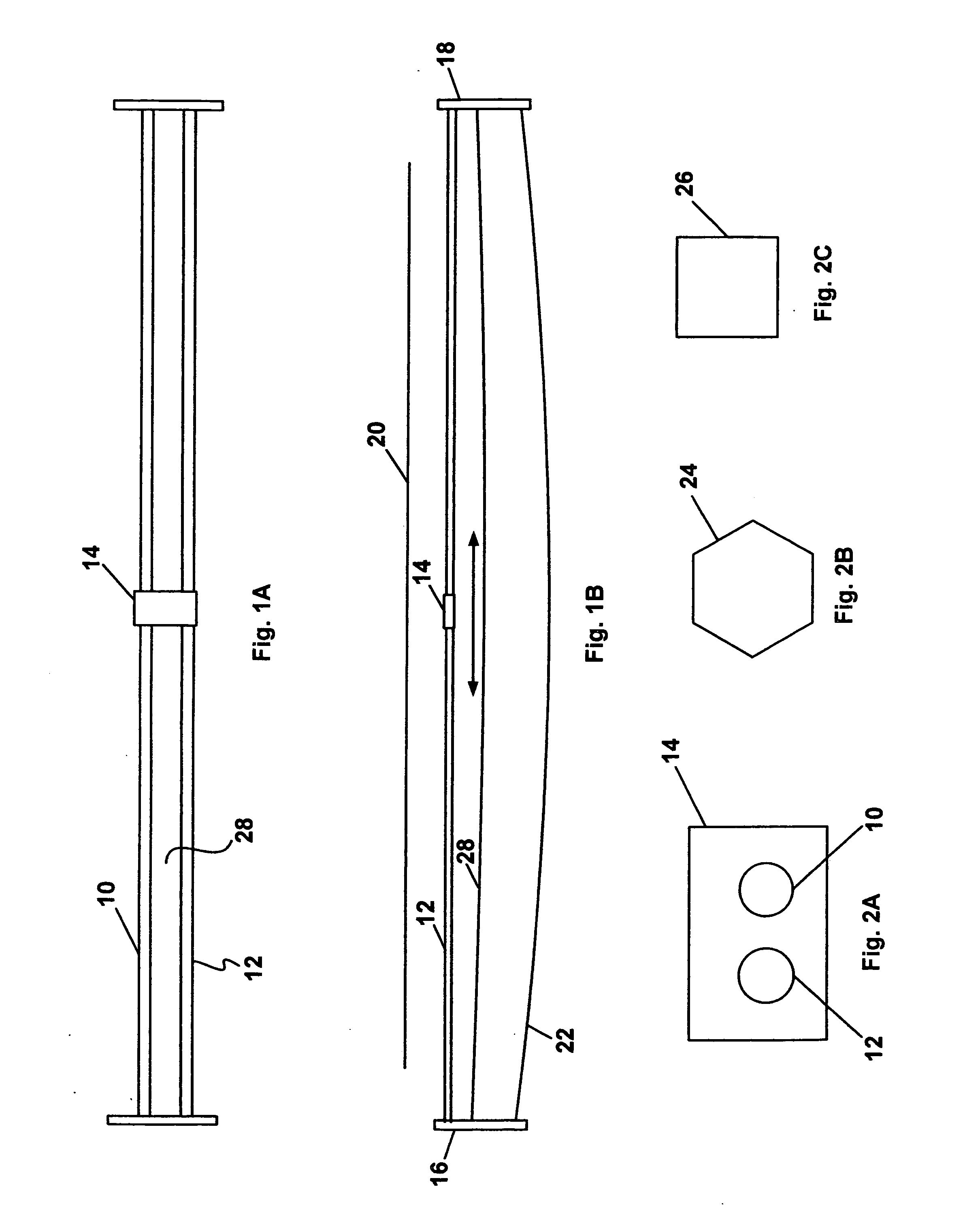
[0027]FIGS. 1A and 1B illustrates an embodiment of the tensioned scanner rail system that includes a tensioned rail that comprises two continuous length flexible guide rods 10, 12 that are secured to arms 16, 18 which project from the ends of the small cross section tension beam or canopy 22. A light weight, mobile device, such as an optical head 14, is supported by the flexible guide rods 10, 12 and scans back-and-forth along the cross direction of the process with application of a drive force as further described herein. Suitable mobile devices include, for example, carriages, detector devices such as optical head or sensor package, and the like. In this example, the mobile optical head 14 is positioned below the sheet of material 20 which moves continuously in the machine direction perpendicular to the path of the optical head 14. It is understood that the optical head can be positioned on either or both sides of the sheet depending on the type of scanner used.

[0028] The ends of...


PUM


Abstract

A rail system made of one or more flexible guide rods, each consisting of a tension rod, is used to support lightweight, mobile devices such as carriages, scanning heads or optical sensors. The rail is configured to permit movement of the mobile device, when driven by an external drive mechanism, along a main scanning direction but prohibits rotational movement of the mobile device. In this fashion, the mobile device remains substantially at the same measured distance from the flat surface of an object, e.g., moving sheet or web, being analyzed.

Description

FIELD OF THE INVENTION [0001] The present invention generally relates to tensioned scanner rails that support a mobile device that traverses back and forth along a linear path and, in particular, relates to scanner rails that employ one or more tension rods to guide a mobile carriage or optical head between front and back ends along a main, linear scanning direction such that the moving carriage or optical head remains at a measured distance from a relatively flat surface that is being analyzed. BACKGROUND OF THE INVENTION [0002] It is often desirable to obtain measurements of selected characteristics of sheet materials during manufacture. Although various properties of sheet materials can be detected by off-line laboratory testing, such tests often are not practical because of the time required for sample acquisition and analysis. Also, laboratory testing has the shortcoming that samples obtained for testing may not accurately represent sheet material that has been produced. [0003]...

Claims


Application Information

Patent Timeline
Patent Type & Authority Applications(United States)
IPC IPC(8): H04N1/04
CPCH04N1/04H04N2201/0456H04N1/128H04N1/103
Inventor BESELT, RONALD E.HARJULA, JOHN A.
Owner HONEYWELL INT INC
Why Eureka
Try Eureka