Optical proximity correction mask and method of fabricating color filter

Active Publication Date: 2007-03-15
UNITED MICROELECTRONICS CORP
View PDF1 Cites 7 Cited by
  • Summary
  • Abstract
  • Description
  • Claims
  • Application Information

AI Technical Summary

Benefits of technology

[0026] In foregoing descriptions about the optical proximity correction mask of the invention, since the optical proximity correction is performed on the mask pattern, the optical proximity effect can be reduced during fabricating the color filter.
[0027] In another aspect, in

Problems solved by technology

The mask pattern and the transferred pattern, being transferred to the color filter,

Method used


Image

  • Optical proximity correction mask and method of fabricating color filter
  • Optical proximity correction mask and method of fabricating color filter
  • Optical proximity correction mask and method of fabricating color filter

Examples


Embodiment Construction

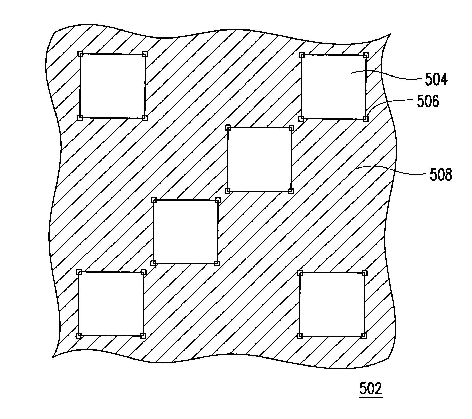
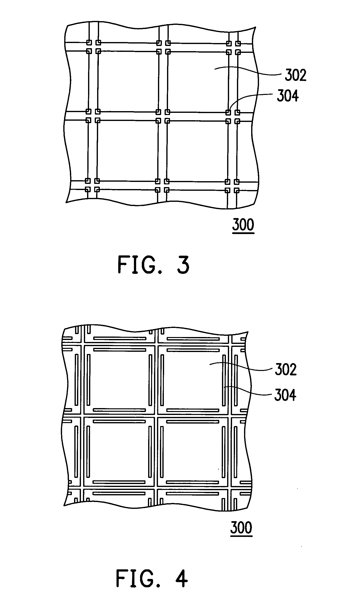
[0037]FIG. 3 is a drawing, schematically illustrating an optical proximity correction mask, according to an embodiment of the invention. FIG. 4 is a drawing, schematically illustrating an optical proximity correction mask, according to another embodiment of the invention. FIG. 5 is a drawing, schematically illustrating the mask pattern and the transferred pattern, according to another embodiment of the invention.

[0038] Referring to FIG. 3 and FIG. 4, the invention provides an optical proximity correction mask, suitable for fabricating a color filter. The color filter has a transferred pattern, which is indicated by 306 in FIG. 5 and is transferred from the mask pattern, such as the elements indicated by 304 in FIG. 3 and FIG. 4. The optical proximity correction mask includes a substrate 300, a mask pattern 302, and a mending pattern 304. Wherein, the mask pattern 302 and the mending pattern 304 are disposed on the substrate 300. A material for the substrate 300 is, for example, tra...


PUM


Abstract

An optical proximity correction mask used for fabricating a color filter includes a substrate, a mask pattern and a mending pattern. Wherein, the mask pattern is disposed on the substrate. The mask pattern and the transferred pattern, being transferred to the color filter, are not matched and cause occurrence of a light leaking region in the color filter. The mending pattern is disposed over the substrate around the periphery of the mask pattern and corresponds to the light leaking region.

Description

BACKGROUND OF THE INVENTION [0001] 1. Field of Invention [0002] The present invention relates to an optical proximity correction mask. More particularly, the present invention relates to an optical proximity correction mask used in fabricating color filter. [0003] 2. Description of Related Art [0004] In accordance with the computer performance being greatly improved as well as the network and the multimedia technology being greatly developed, most of the current image information has been converted from analogue to digital and then is transmitted. In order to associate with the modem life, size of the video or the image device has been greatly reduced to be thin and light. The conventional cathode-ray tube (CRT) display has its advantages but this display occupies a large space due to the structure of the internal electron cavity. For the additional issue, it has the radiation during operation, causing damage on eye. Thus, the flat panel display has been developed, based on the opto...

Claims


Application Information

Patent Timeline
IPC IPC(8): G02B5/20G03F1/00
CPCG02B5/201G03F1/36G03F1/144G02B5/223
Inventor WU, HSIN-PINGLIN, CHIA-HUEI
Owner UNITED MICROELECTRONICS CORP
Why Eureka
Try Eureka