Hot plug wire contact and connector assembly

Inactive Publication Date: 2007-03-15
TE CONNECTIVITY CORP
View PDF12 Cites 24 Cited by
  • Summary
  • Abstract
  • Description
  • Claims
  • Application Information

AI Technical Summary

Problems solved by technology

Connecting and breaking load currents in such a system, however, presents a number of challenges.
For example, making and breaking of the electrical connection under load conditions may result in intense energy discharges within the connector system as the connector contacts are engaged and disengaged.
For example, known lighting systems may operate at voltages of 277 V to 600 V, and may experience currents of 1-5 A in normal operation Most commercially available connectors are not suited for completing and breaking such connections under load.
In particular, energy disch

Method used


Image

  • Hot plug wire contact and connector assembly
  • Hot plug wire contact and connector assembly
  • Hot plug wire contact and connector assembly

Examples


first embodiment

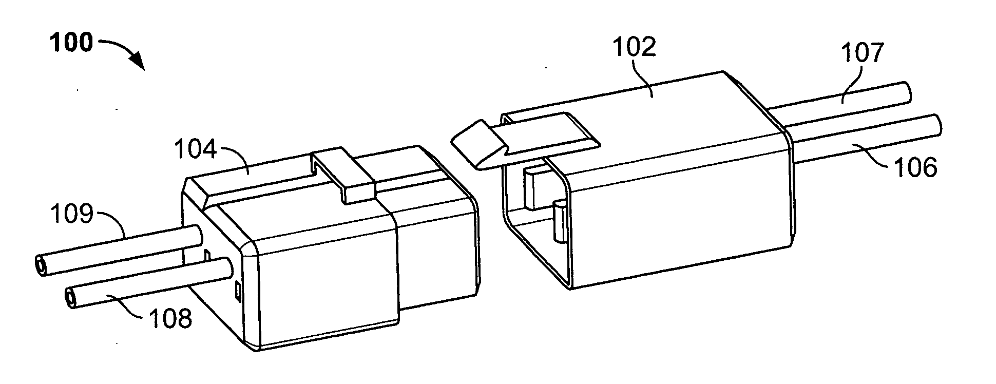
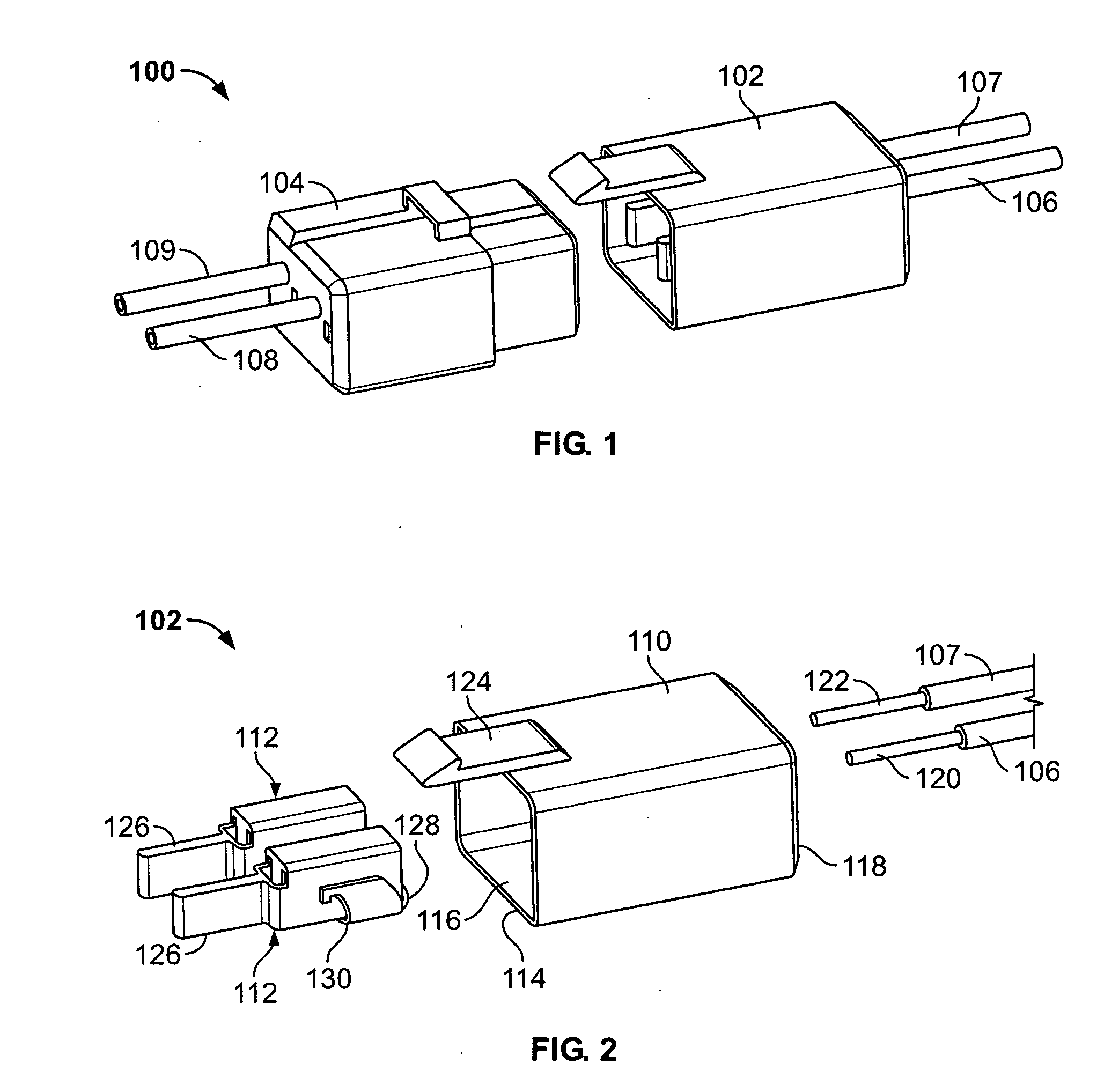
[0033]FIG. 1 is a perspective view of an exemplary connector assembly 100 formed in accordance with an exemplary embodiment of the invention and arranged in an unplugged or unmated condition. The connector assembly 100 includes a male connector 102 and a female connector 104 interconnecting first and second load wires 106, 107 with respective first and second line wires 108, 109.

[0034] As explained below, the connector assembly 100 permits connection of the load wires 106, 107 and the line wires 108, 109 that requires minimal time and effort to complete. Moreover, the connectors may be engaged and disengaged to reliably complete and break electrical interconnection of the wires 106, 107 and 108, 109 while the wires are energized and still under electrical load. That is, the connector assembly 100 is operable without de-energizing the associated circuitry, sometimes referred to herein as “hot plugging.”

[0035]FIG. 2 is an exploded view of the male connector 102 including a housing 110...

second embodiment

[0046]FIG. 6 and 7 are a perspective view and a sectional view, respectively, of an exemplary connector assembly 200 in an unplugged or unmated position. The assembly 200 is similar to the assembly 100 is some aspects, and like reference characters of the assembly 100 are utilized in FIG. 5 to denote like features of the connector assembly 200.

[0047] The assembly 200 includes the female connector 104 and the male connector 102 substantially as described above, except that the male connector 102 includes contacts having right angle legs 202 so that the male connector 102 may be mounted to a circuit board 204 with known through-hole mounting techniques. The right angle legs 202 may be formed with the aforementioned contacts 112 via known stamping and formation techniques, and as shown in FIG. 7, the contact legs 202 are extended through the circuit board 204 to establish electrical connection therewith. The assembly 200 is otherwise constructed and operates substantially similar to th...


PUM


Abstract

An electrical connector and contact includes a contact body having an axial length, a termination section extending from the body, a first primary contact beam extending from the body and spaced from the body by a first axial length, and a sacrificial leading contact beam extending from the body for a second axial length. The second length is greater than the first length, and a distal end of the contact beam is configured to complete or break an energized electrical connection with a mating contact.

Description

BACKGROUND OF THE INVENTION [0001] This invention relates generally to electrical connectors, and, more particularly, to separable electrical connectors operable under energized electrical load current conditions. [0002] In certain installations, such as interconnection of lighting ballasts for fluorescent lights, it is desirable to connect or disconnect lighting ballasts in an energized electrical system. Ballasts may therefore be connected or disconnected to the electrical system by plugging and unplugging electrical connectors without having to de-energize or shut down some or all of the electrical system. Thus, with convenient plug connectors, a lighting system may be safely and more easily replaced when lighting requirements change. Thus, for example, lighting ballasts may be added or removed to an existing lighting system with plug-in connection. Connecting and breaking load currents in such a system, however, presents a number of challenges. [0003] For example, making and bre...

Claims


Application Information

Patent Timeline
IPC IPC(8): H01R13/58
CPCH01R13/113H01R13/112
Inventor FABIAN, DAVID JAMESLANDIS, JOHN MICHAELDAILY, CHRISTOPHER G.KOCHER, TIMOTHY LEE
Owner TE CONNECTIVITY CORP
Why Eureka
Try Eureka