Hand-Held Power Tool With Clamping Device For A Tool

a technology of clamping device and power tool, which is applied in the direction of grinding machine components, grinding machines, sawing apparatus, etc., can solve the problems of large abrupt torque in both directions, inability to ensure that the tool is clamped sufficiently securely with the known clamping device, and insufficient clamping force that can be achieved in many applications. achieve the effect of simple and reliable manner

Active Publication Date: 2007-03-15
C & E FEIN GMBH & CO KG
View PDF17 Cites 74 Cited by
  • Summary
  • Abstract
  • Description
  • Claims
  • Application Information

AI Technical Summary

Benefits of technology

[0008] It is a first object of the invention to disclose a hand-held power tool that enables a tool to be fastened to the work spindle in a simple and reliable manner without having to use an auxiliary tool such as a spanner or the like.
[0009] It is a second object of the invention to disclose a hand-held power tool that enables a tool to be fastened to the work spindle in a simple and reliable manner with a strong clamping force that is sufficient to ensure reliable and secure clamping of the tool even under heavy loads.
[0010] It is a third object of the invention to disclose a hand-held power tool that enables a tool to be fastened to the work spindle in a simple and reliable manner with a strong clamping force that is sufficient to ensure reliable and secure clamping of the tool even under oscillating loads such as those which occur in appliances driven by an oscillating drive.

Problems solved by technology

If the tool is driven by an oscillating drive means such that it oscillates back and forth about the longitudinal axis of the work spindle, this results in large abrupt torques in both directions of rotation and with great impetus, with the result that it is not possible with the known clamping device to ensure that the tool is clamped sufficiently securely.
Although the various solutions known from this document are essentially suitable for clamping a tool onto a work spindle without using an accessory, it has been found that the clamping forces that can be achieved here are likewise inadequate for many applications.

Method used


Image

  • Hand-Held Power Tool With Clamping Device For A Tool
  • Hand-Held Power Tool With Clamping Device For A Tool
  • Hand-Held Power Tool With Clamping Device For A Tool

Examples


Embodiment Construction

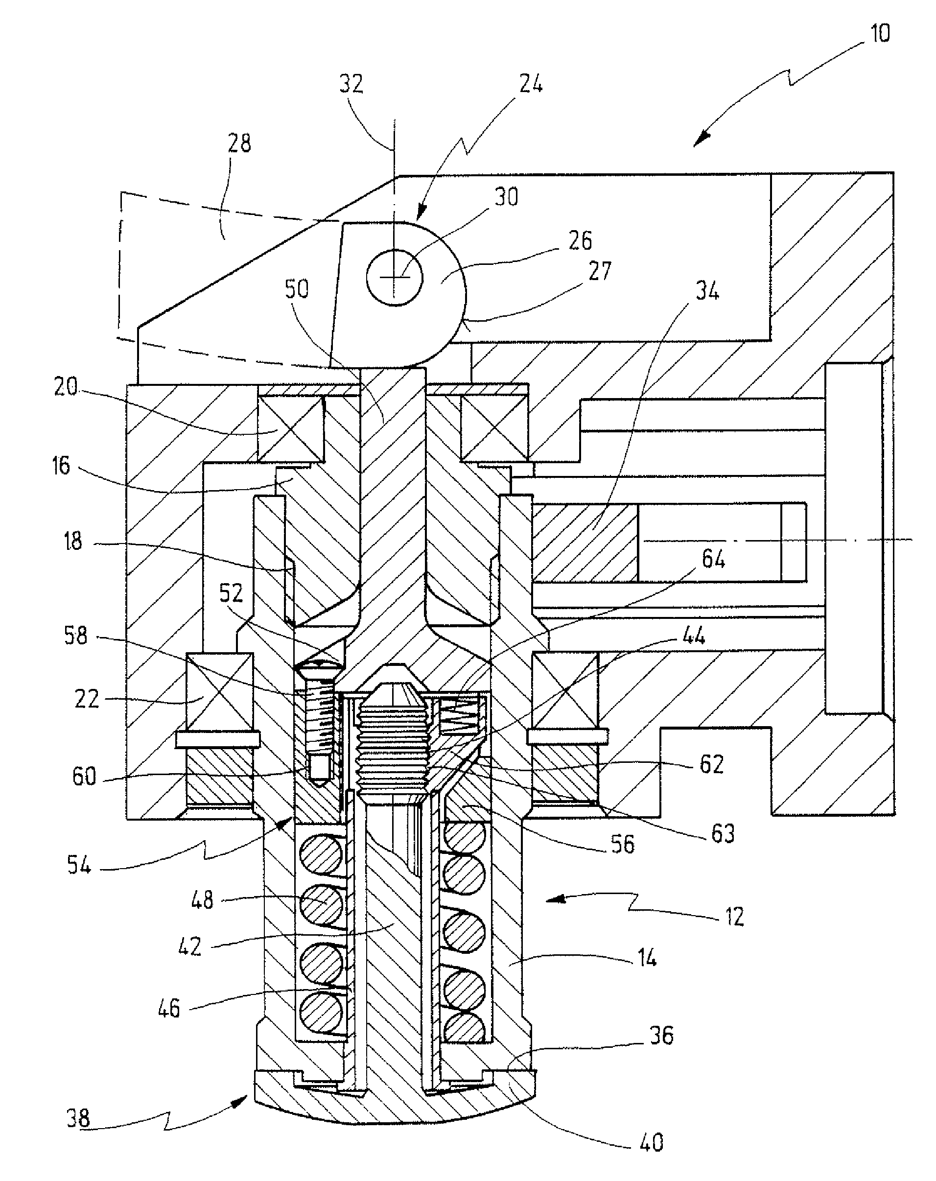
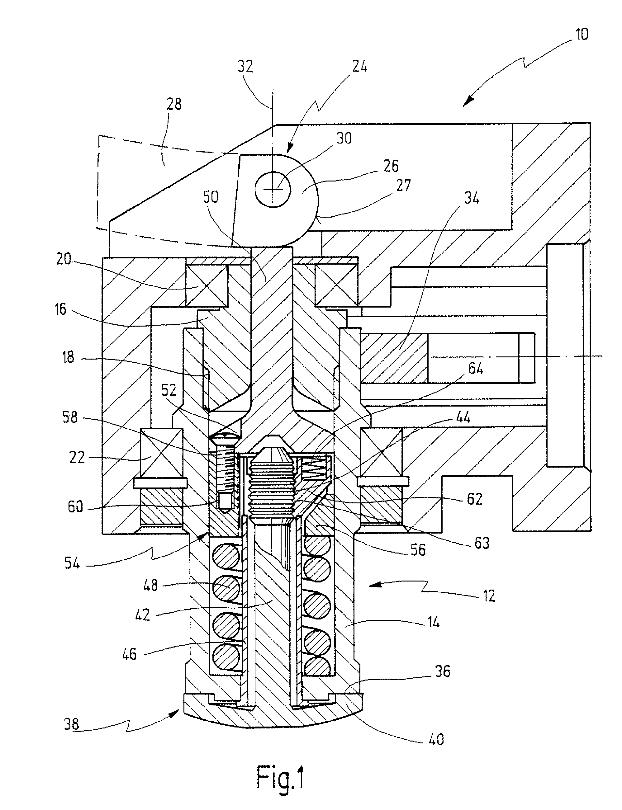
[0057]FIG. 1 shows the gearhead region of a hand-held power tool according to the invention, said power tool being labeled in its entirety with reference numeral 10. Hand-held tool 10 has an oscillating drive for driving a tool in an oscillating manner with a small pivot angle and high frequency about the longitudinal axis 32 of a work spindle 12. Such oscillating drives are used to perform numerous special kinds of work, including cutting out the panes of a motor vehicle using an oscillatingly driven blade, sawing with oscillatingly driven serrated blades, grinding, and many other kinds of work.

[0058] In contrast to rotating work spindles, large abrupt torques in both directions of rotation and with great impetus occur when work spindles are oscillatingly driven. Very strong clamping forces (in a relatively small construction space) and a robust backlash-free mechanism are necessary to ensure that tools are held on the work spindle under all operating conditions.

[0059] These requ...


PUM

PropertyMeasurementUnit
apex angleaaaaaaaaaa
claming forceaaaaaaaaaa
forceaaaaaaaaaa

Abstract

A hand-held power tool (10) is specified, comprising a work spindle (12) for driving a tool (68), said tool (68) being fastenable between a fastening element (38) and a holding portion (36) on a tool end of the work spindle (12), and a displacement device (24) for sliding the fastening element (38) between a released position in which the fastening element (38) can be detached from the work spindle (12) and a clamped position in which the fastening element (38) is clamped against the holding portion (36) by a spring element (48). The fastening element (38) includes a clamping shaft (42) that is insertable into the work spindle (12) and held in the clamped position by a lock assembly (54) inside the work spindle (12), and which can be removed when in the released position (FIG. 2).

Description

CROSS REFERENCES TO RELATED APPLICATIONS [0001] This application is a continuation of International Patent Application PCT / EP2005 / 003794, filed on Apr. 12, 2005 designating the U.S., which International Patent Application has been published in German language and claims priority of German patent application 10 2004 020 982.0, filed on Apr. 23, 2004, the entire contents of which is incorporated herein by reference.BACKGROUND OF THE INVENTION [0002] The invention relates to a hand-held power tool comprising a work spindle for driving a tool, said tool being fastenable between a fastening element and a holding portion on a tool end of the work spindle, and a displacement device for sliding the fastening element between a released position in which the fastening element can be detached from the work spindle and a clamped position in which the fastening element is clamped against the holding portion by a spring element. [0003] A hand-held power tool comprising a clamping device for manua...

Claims


Application Information

Patent Timeline
Patent Type & Authority Applications(United States)
IPC IPC(8): B24B27/08B24B45/00B27B5/32
CPCB27B5/32B24B45/006Y10T83/9464
Inventor POLLAK, ROLANDZIEGLER, ROLF
Owner C & E FEIN GMBH & CO KG
Why Eureka
Try Eureka