Vehicle differential including pump with variable-engagement clutch

a technology of variable-engagement clutch and differential, which is applied in the direction of mechanical equipment, transportation and packaging, etc., can solve the problems of shortening the useful life of hydraulic fluid, negatively affecting the fuel economy of vehicles,

Active Publication Date: 2007-03-15
EATON INTELLIGENT POWER LIMITED
View PDF8 Cites 3 Cited by
  • Summary
  • Abstract
  • Description
  • Claims
  • Application Information

AI Technical Summary

Problems solved by technology

The parasitic energy losses generated by the continually operating pump can negatively impact vehicle fuel economy and shorten the useful life of the hydraulic fluid.

Method used


Image

  • Vehicle differential including pump with variable-engagement clutch
  • Vehicle differential including pump with variable-engagement clutch
  • Vehicle differential including pump with variable-engagement clutch

Examples


Embodiment Construction

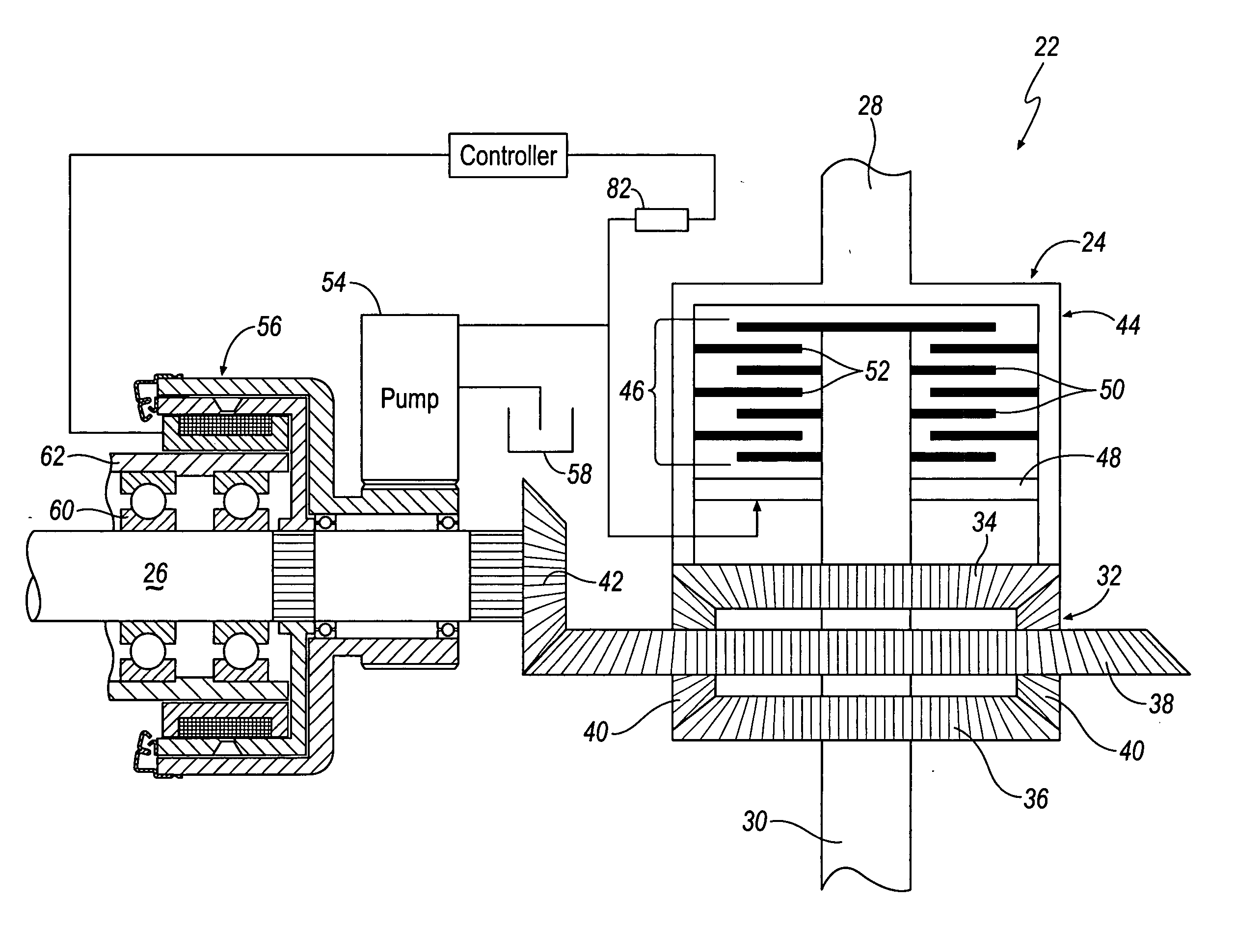
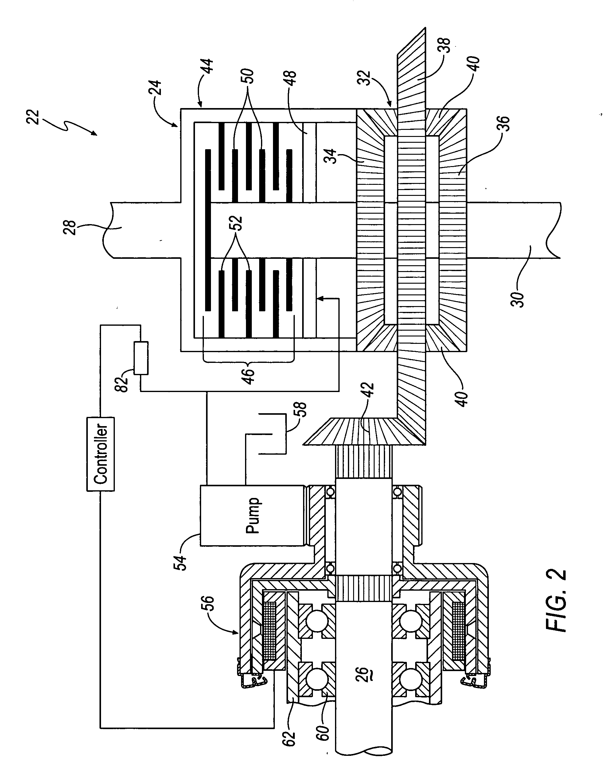
[0015] Referring now to the drawings, several embodiments of the present invention are shown. The drawings are not necessarily to scale and certain features may be simplified or exaggerated to better illustrate and explain the present invention. Further, the embodiments set forth herein are not intended to be exhaustive or otherwise limit or restrict the invention to the precise configurations shown in the drawings and disclosed in the following detailed description.

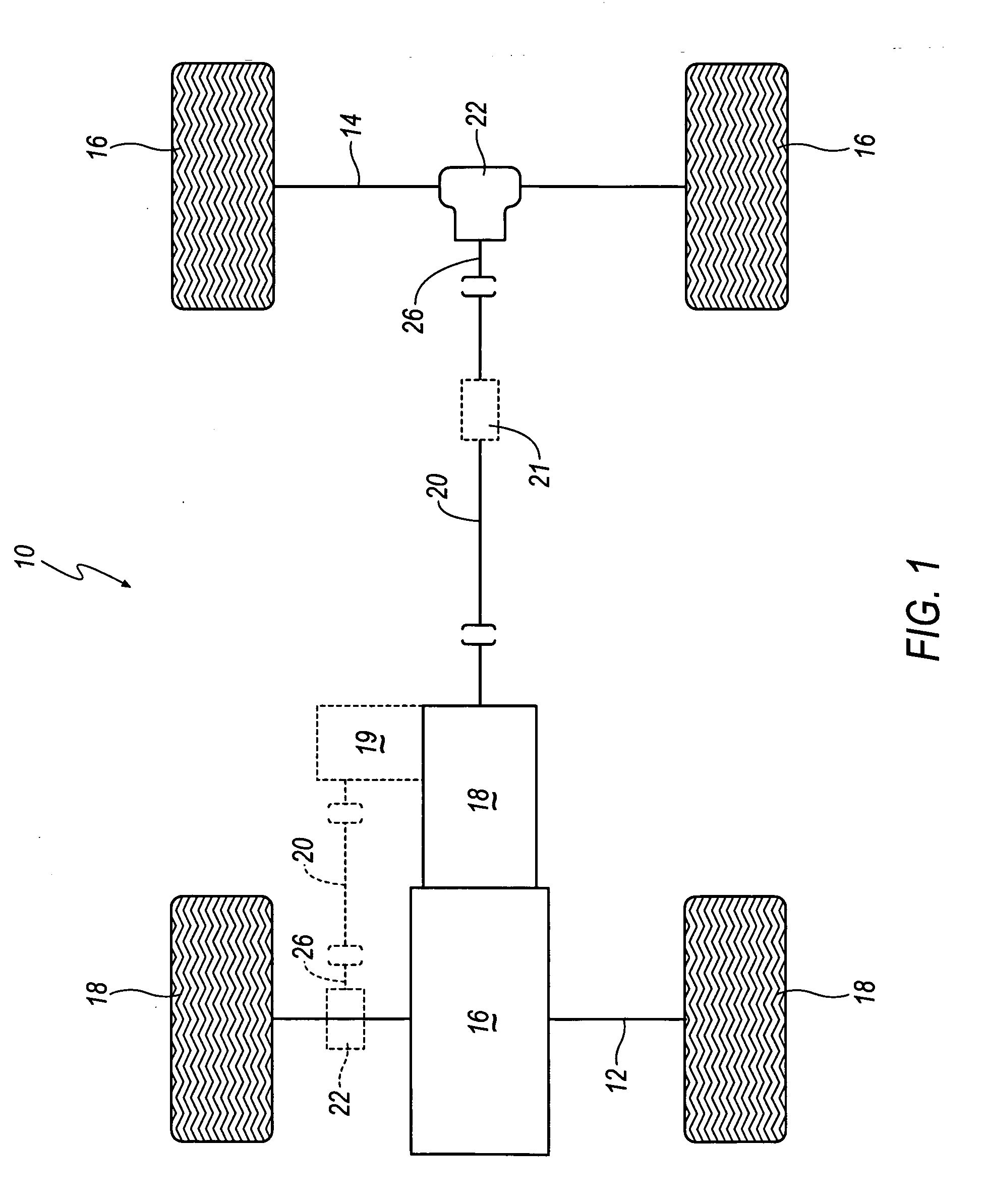
[0016] Referring to FIG. 1, an exemplary automotive vehicle 10, such as a passenger car, sport utility vehicle or light truck, is shown that includes first and second vehicle axles 12 and 14, respectively, a prime mover 16, such as an internal combustion engine, and a power transmission mechanism 18. In the illustrated embodiment, second axle 14 serves as the primary vehicle-propelling drive axle to which primary drive wheels 16 are operatively connected. In contrast, first axle 12 serves as a secondary axle to which a ...


PUM


Abstract

A vehicle differential assembly is provided that includes a differential driven by an input and adapted to allow differing rotational speed between a pair of outputs. The differential includes a gear assembly connected to the outputs and a hydraulically-actuated clutch for selectively and variably coupling the outputs. A hydraulic pump is adapted to generate hydraulic fluid pressure for engagement of the hydraulically-actuated clutch. A variable-engagement clutch is operatively connected to the input and the hydraulic pump such that the input selectively drives the hydraulic pump during engagement of the clutch to provide hydraulic fluid pressure to the hydraulically-actuated clutch. A torque coupling including a variable-engagement clutch is also provided.

Description

BACKGROUND OF THE INVENTION [0001] 1. Field of the Invention [0002] The present invention relates to a vehicle differential and to a vehicle differential including a hydraulic pump with a variable-engagement clutch. [0003] 2. Description of the Related Art [0004] Differentials are provided on vehicles to permit an outer drive wheel to rotate faster than an inner drive wheel during cornering as both drive wheels continue to receive power from the engine. While differentials are useful in cornering, they can allow vehicles to lose traction, for example, in snow or mud or other slick mediums. If either of the drive wheels loses traction, it will spin at a high rate of speed and the other wheel may not spin at all. To overcome this situation, limited-slip differentials were developed to shift power from the drive wheel that has lost traction and is spinning to the drive wheel that is not spinning. [0005] Recently, an electronically-controlled, limited-slip differential has been introduc...

Claims


Application Information

Patent Timeline
Patent Type & Authority Applications(United States)
IPC IPC(8): F16H48/06
CPCF16D29/00F16D37/02F16D43/28F16H48/08F16H48/22F16H2200/2071F16H48/32F16H48/34F16H2048/204F16H2048/423F16H48/30
Inventor BODDY, DOUGLAS E.
Owner EATON INTELLIGENT POWER LIMITED
Why Eureka
Try Eureka