Digital core workflow method using digital core image

a workflow method and digital core technology, applied in the field of formation depth determination methods, can solve the problems of inability to accurately determine the depth of the formation, easy errors, and time-consuming labeling process, and achieve the effects of reducing time expenditure, reducing labor intensity, and reducing labor intensity

Inactive Publication Date: 2007-03-15
H & H CONSULTING
View PDF5 Cites 44 Cited by
  • Summary
  • Abstract
  • Description
  • Claims
  • Application Information

AI Technical Summary

Benefits of technology

[0087] The use of digital core images during depth registration, rather than reliance on the presence of physical core samples, provides tremendous advantages for geologists and the companies they work for, particularly when this is linked to the use of the Internet for access and dissemination of information. While digital images have been used in the past to summarize core logging information, and occasionally for comparison against well logging data during depth correction processes, the advantage of using digital core images in depth registration is a novel development in the field.
[0088] A method according to the present invention requires fewer personnel, with time expenditure reduced substantially when compared with traditional methods. All information, including well logs and cores, is provided in digital form and can therefore be easily manipulated, analyzed, and distributed to others. The geologist need no longer be confined to a laboratory setting to engage in core logging, but c

Problems solved by technology

During drilling, core depths are recorded by workers on a drilling rig, but very often they are not accurate (off-depth), and the geologist is faced with the task of attempting to determine depth information based on rock that has already been brought to surface.
The manual, hard-coded labelling is a very time-consuming process and prone to errors; it also makes any updating of labels extremely difficult, especially when the geologist changes a depth.
As is abundantly clear from the foregoing, there are numerous disadvantages to the traditional physical core workflow: 1) Several people are necessarily involved.
The more people that are involved, the harder it is to co-ordinate and the more opportunities there are for mistakes.
There are more inherent

Method used


Image

  • Digital core workflow method using digital core image
  • Digital core workflow method using digital core image
  • Digital core workflow method using digital core image

Examples


Embodiment Construction

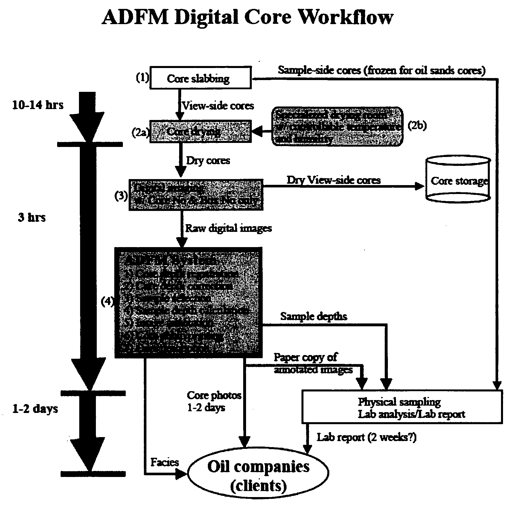
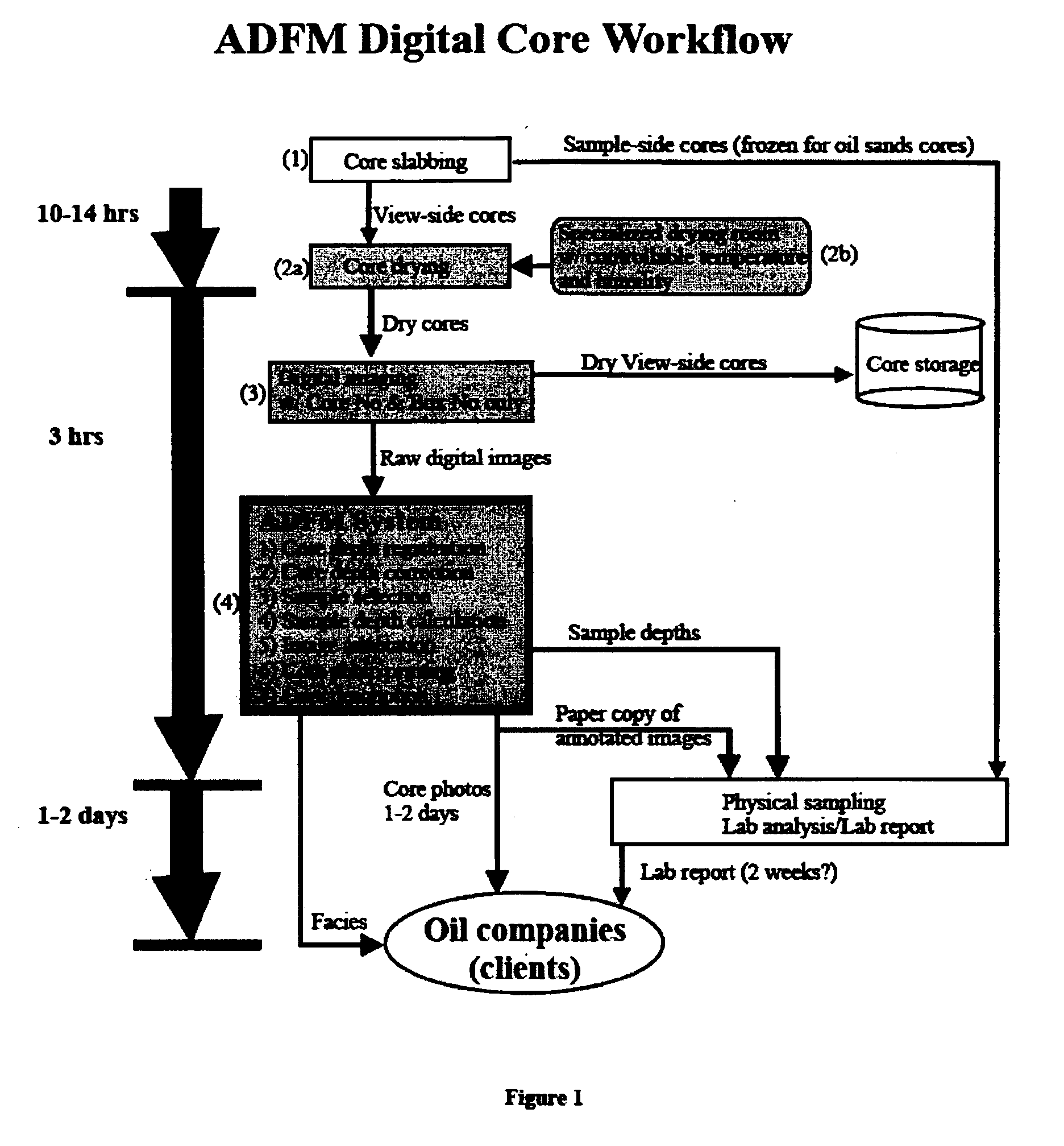
[0123] A preferred embodiment of the present invention will now be described with reference to the accompanying drawings. The preferred embodiment of the present invention will be described below by reference to an overall digital core workflow, which digital core workflow comprises a method and system referred to as ADFM™ (an acronym for “Accurate Depths for Facies and Modeling”).

Digital Core Workflow

[0124] Referring now in detail to FIG. 1, a digital core workflow is illustrated in accordance with the present invention. As can be seen, after cores (which may be frozen) are slabbed into two halves at step 1, the view-side cores are placed at step 2a into a specialized drying room 2b for approximately 10 to 14 hours to dry the cores, instead of simply displaying the cores in an ordinary core-view room. The specialized drying room 2b is tightly sealed after the doors are dosed and is separated from other ordinary view rooms or office rooms. The temperature in the room is settable,...


PUM


Abstract

A method for registration and correction of downhole core depth information using digital core images. Digital core images are employed during depth registration, with top and base depths for a selected interval being determined by field data and a digital ruler which calculates an actual interval length based on the digital core image. Correction of the top and base depths is enabled by side-by-side display of the digital core image interval and corresponding well logging data, which displayed information can be manipulated by a user to provide more accurate depth information. The method further allows for shale volume calculations and facies interpretation, again employing the digital core images.

Description

FIELD OF THE INVENTION [0001] The present invention relates to methods for determining formation depths, and more particularly to core logging methods. BACKGROUND OF THE INVENTION [0002] Although relatively expensive, coring—the taking of subsurface rock samples with specialized drilling tools—is one of the oldest methods of subsurface formation evaluation and the only method (other than cuttings analysis) for providing rock samples for laboratory analysis. Coring is used to provide geologists and other earth scientists with physical rock samples that can provide much-needed information on a direct rather than indirect basis. [0003] A core bit is used to cut a generally cylindrical section of rock that is contained within a coring tube, which section within the tube is then brought to surface (any expected portion of the core that does not make it back to surface is considered to be “lost core”). The core tube is marked with a well name, core number, and subsurface interval depths a...

Claims


Application Information

Patent Timeline
IPC IPC(8): E21B47/00E21B47/04
CPCE21B47/04E21B25/00
Inventor HU, YUANXIAN GREG
Owner H & H CONSULTING
Why Eureka
Try Eureka