Flowmeter

a flowmeter and flow path technology, applied in the field of flowmeters, can solve the problems of difficult attachment of the flowmeter to the pipeline, significant directional changes in the flow path, etc., and achieve the effects of simple installation of the flowmeter, reduced manufacturing costs, and reduced manufacturing costs

Inactive Publication Date: 2007-03-22
GEBRUDER MULLER APPARATEBAU GMBH & CO KG
View PDF4 Cites 14 Cited by
  • Summary
  • Abstract
  • Description
  • Claims
  • Application Information

AI Technical Summary

Benefits of technology

[0018] A flowmeter according to the present invention has many advantages. The flow of fluid is routed between a pipeline and a connecting pipe with only minor changes in flow directions so that the Kv value can be increased in particular in the attachment zone to the pipeline. The disposition of the transducers at the end surfaces of the measuring tube produces accurate measurement of the flow velocity and flow rate of the fluid flowing in the pipeline. Installation of the flowmeter is simple and requires little space as a consequence of the flat construction of the flowmeter. Manufacture is also simple and cost-saving as a result of the symmetric configuration.

Problems solved by technology

This approach caused problems because it resulted in significant directional changes of the fluid flow path since the ultrasonic transducers take up the space at the end surfaces of the measuring tube.
In addition, attachment of the flowmeter to the pipeline is made more difficult.

Method used


Image

  • Flowmeter
  • Flowmeter
  • Flowmeter

Examples


Embodiment Construction

[0024] Throughout all the Figures, same or corresponding elements are generally indicated by same reference numerals. These depicted embodiments are to be understood as illustrative of the invention and not as limiting in any way. It should also be understood that the drawings are not necessarily to scale and that the embodiments are sometimes illustrated by graphic symbols, phantom lines, diagrammatic representations and fragmentary views. In certain instances, details which are not necessary for an understanding of the present invention or which render other details difficult to perceive may have been omitted.

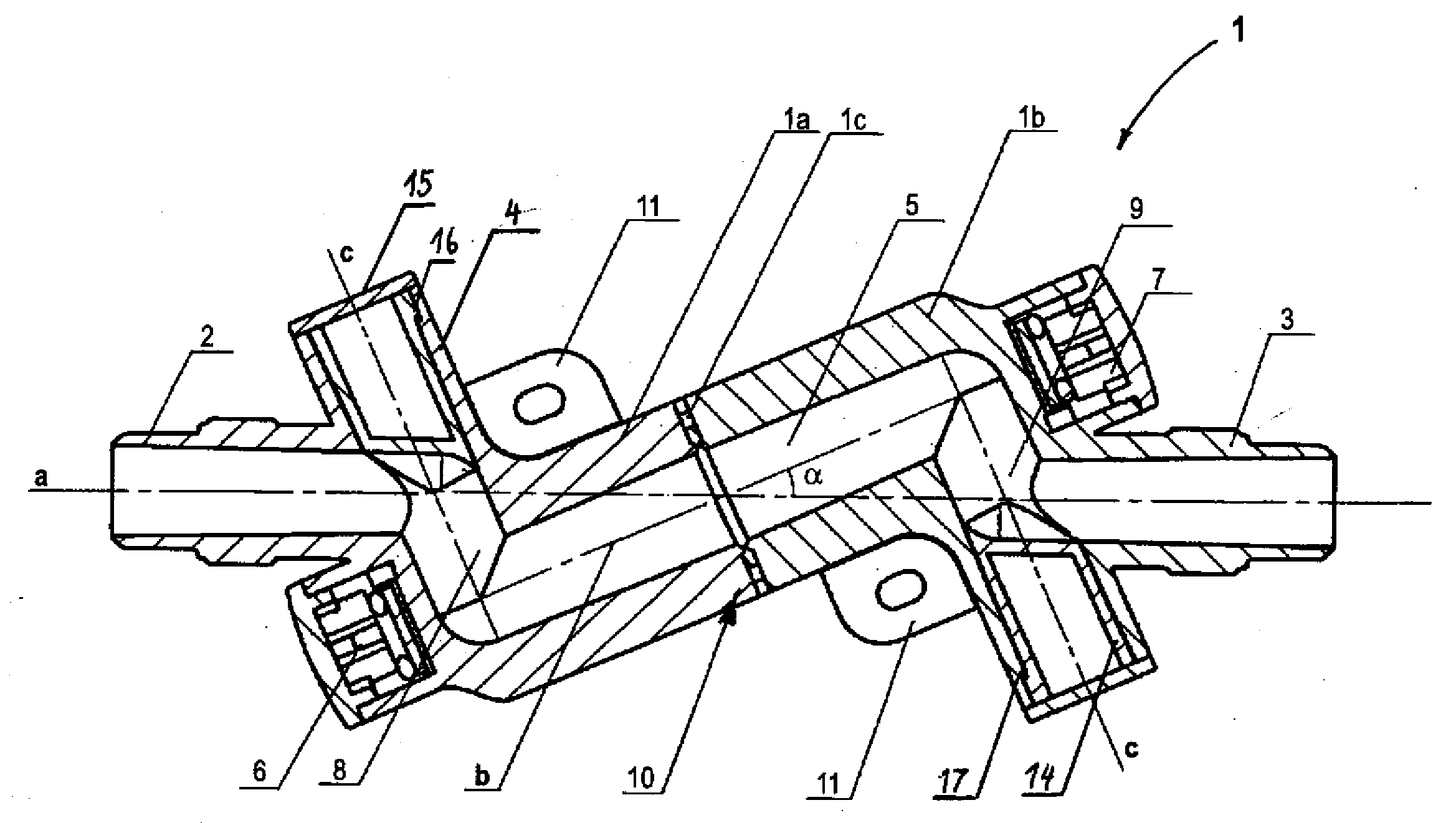
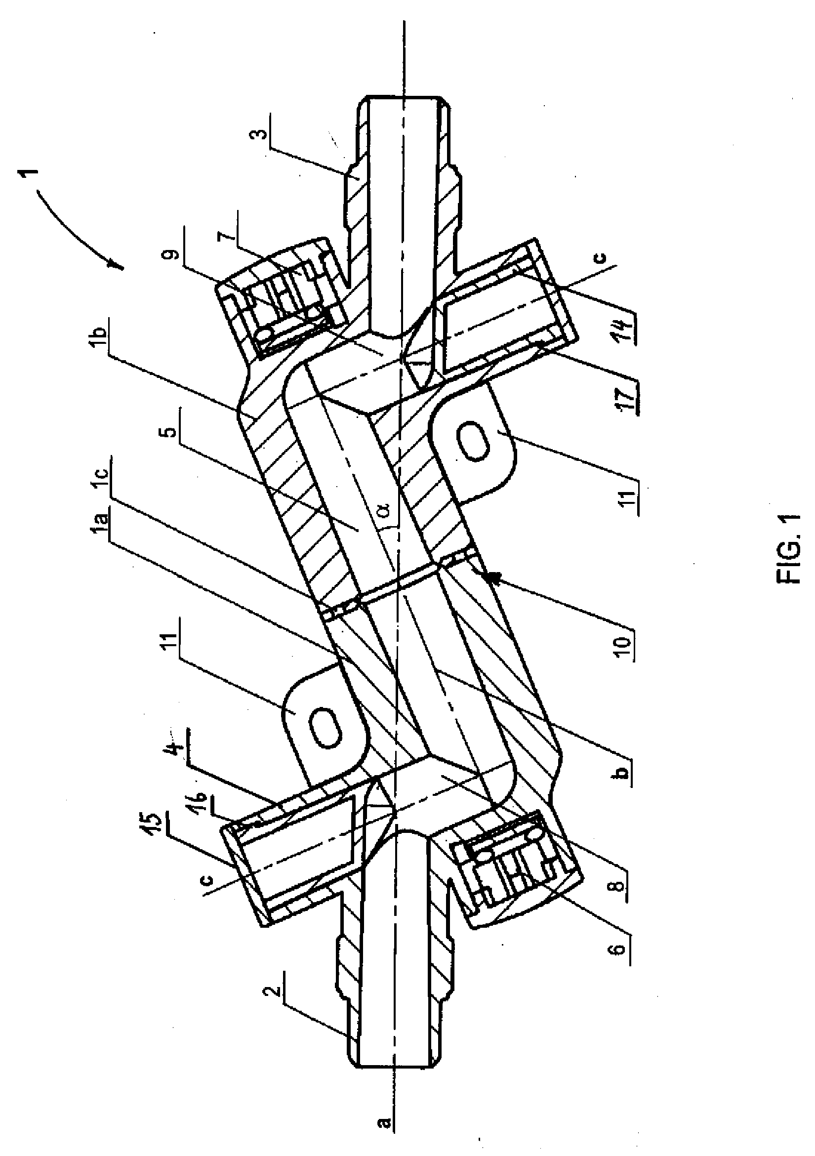
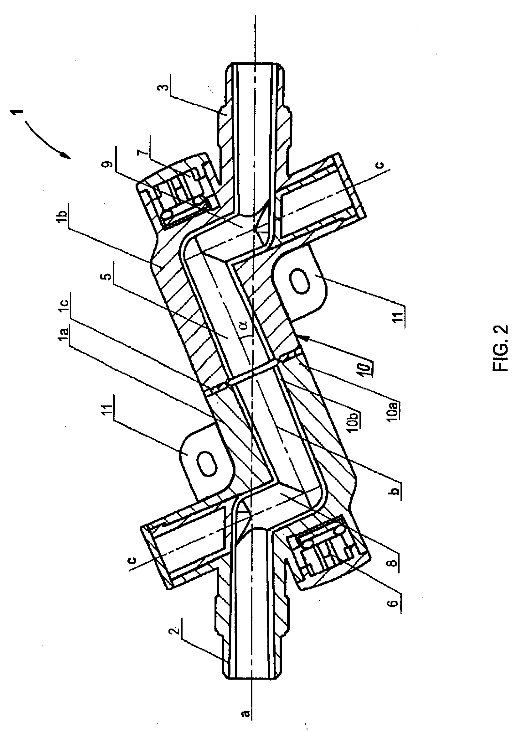
[0025] Turning now to the drawing, and in particular to FIG. 1, there is shown a longitudinal section of one embodiment of a flowmeter according to the present invention, generally designated by reference numeral 1. The flowmeter 1 includes a housing, generally designated by reference numeral 10 and constructed to form a measuring tube 5 which is defined by an axis b. Dispos...


PUM


Abstract

A flowmeter for measuring a flow velocity of a fluid in a pipeline includes a measuring tube having opposite ends. Two ultrasonic transducers are disposed respectively at the opposing ends of the measuring tube, and two connection pipes are provided for attachment of the flowmeter to the pipeline and extend in axial relationship to the pipeline.

Description

CROSS-REFERENCES TO RELATED APPLICATIONS [0001] This application claims the priority of German Patent Application, Serial No. 10 2005 041 288.2, filed Aug. 31, 2005, pursuant to 35 U.S.C. 119(a)-(d), the content of which is incorporated herein by reference. BACKGROUND OF THE INVENTION [0002] The present invention relates to a flowmeter for measuring a flow velocity and a resultant flow rate of a fluid flowing in a pipeline. [0003] Nothing in the following discussion of the state of the art is to be construed as an admission of prior art. [0004] Flowmeters typically include a measuring tube and ultrasonic transducers which are constructed as transmitter / receiver units and mounted to the side of the measuring tube. Ultrasonic radiation is emitted at an angle through the fluid flowing in the measuring tube alternatingly in two directions, namely in flow direction and in opposition to the flow direction, in order to determine the flow velocity on the basis of a change in the running tim...

Claims


Application Information

Patent Timeline
Patent Type & Authority Applications(United States)
IPC IPC(8): G01F1/66
CPCG01F1/662G01F15/185G01F15/14G01F1/667
Inventor MULLER, FRITZ
Owner GEBRUDER MULLER APPARATEBAU GMBH & CO KG
Why Eureka
Try Eureka