Method of measuring cardiac related parameters non-invasively via the lung during spontaneous and controlled ventilation

a cardiac related and non-invasive technology, applied in the direction of respiratory organ evaluation, operating means/release devices for valves, diagnostic recording/measuring, etc., can solve the problems of reducing the accuracy of measured and calculated, and destroying the effect of all

Inactive Publication Date: 2007-03-22
THORNHILL SCI INC
View PDF7 Cites 114 Cited by
  • Summary
  • Abstract
  • Description
  • Claims
  • Application Information

AI Technical Summary

Benefits of technology

[0128] 9. make all calculations without a requirement to measure breat...

Problems solved by technology

A small degree of mixing of FGS with SGS during the latter part of inhalation will reduce accuracy of the measured and calculated results.
Ma...

Method used


Image

  • Method of measuring cardiac related parameters non-invasively via the lung during spontaneous and controlled ventilation
  • Method of measuring cardiac related parameters non-invasively via the lung during spontaneous and controlled ventilation
  • Method of measuring cardiac related parameters non-invasively via the lung during spontaneous and controlled ventilation

Examples


Embodiment Construction

Detailed Description of the Apparatus

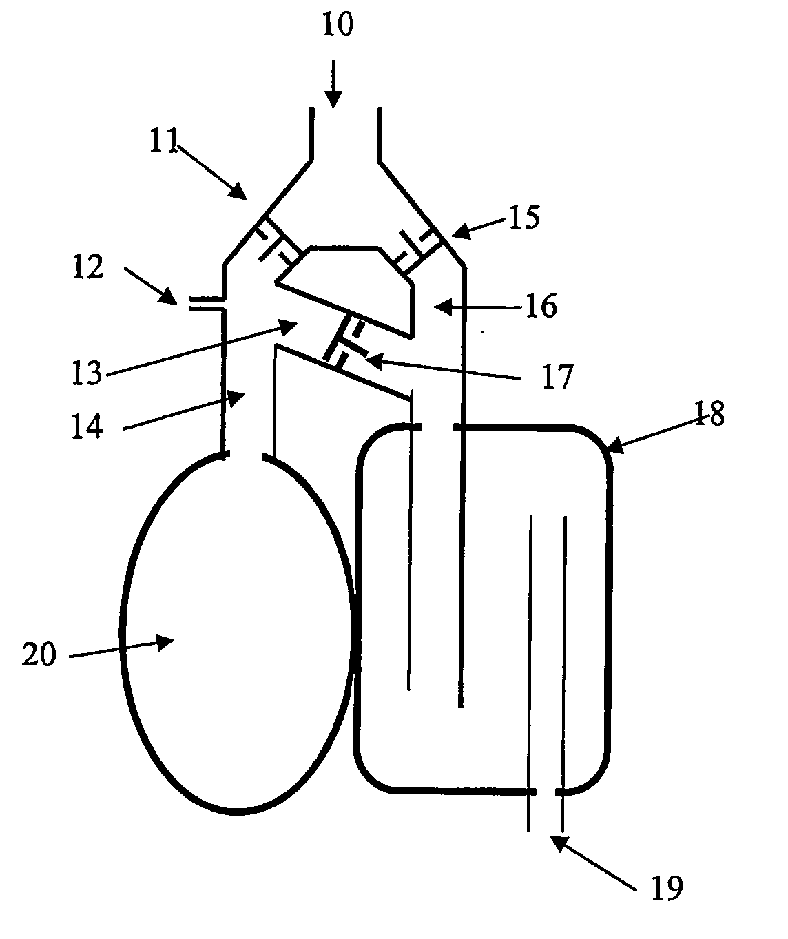
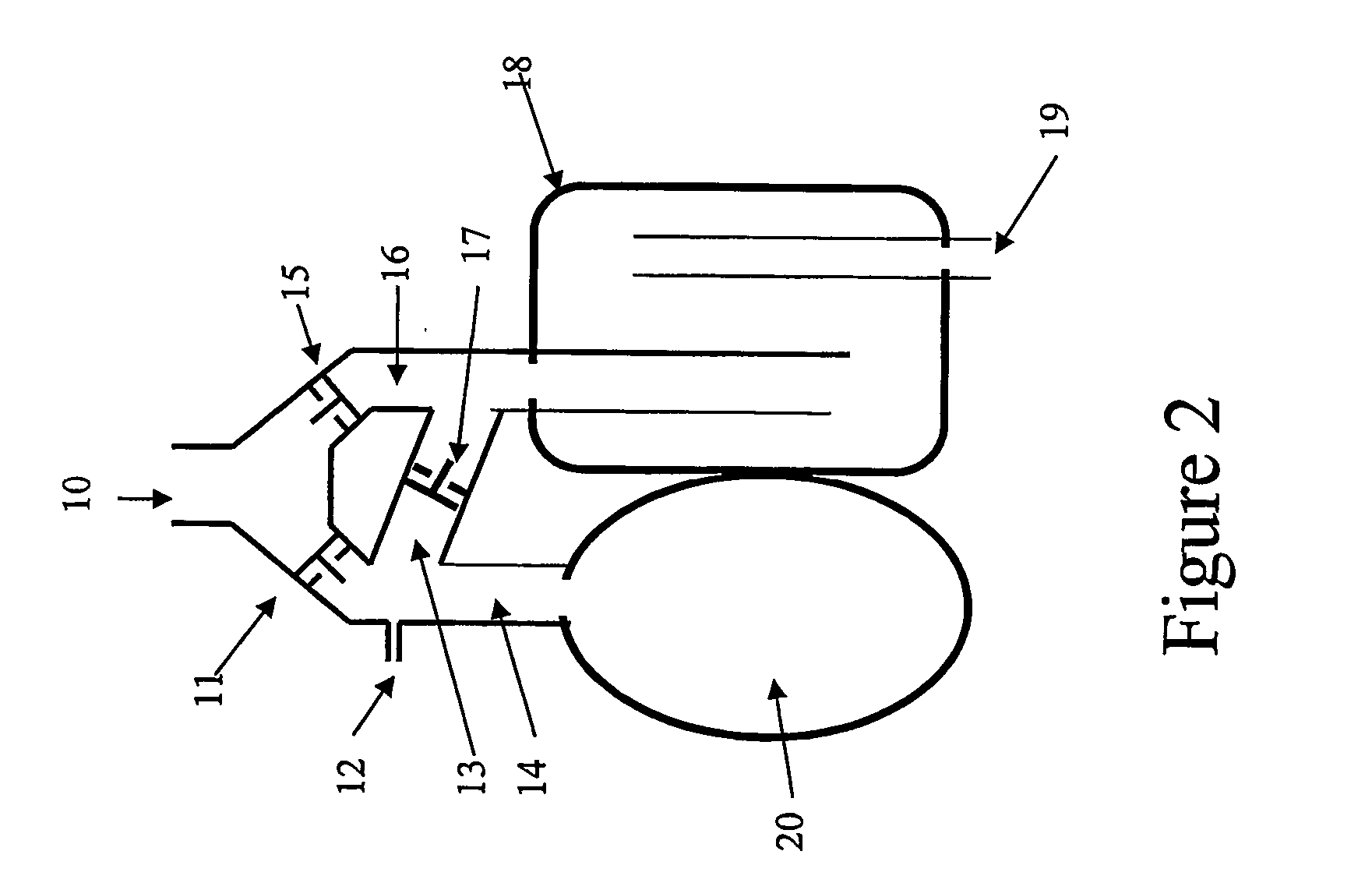
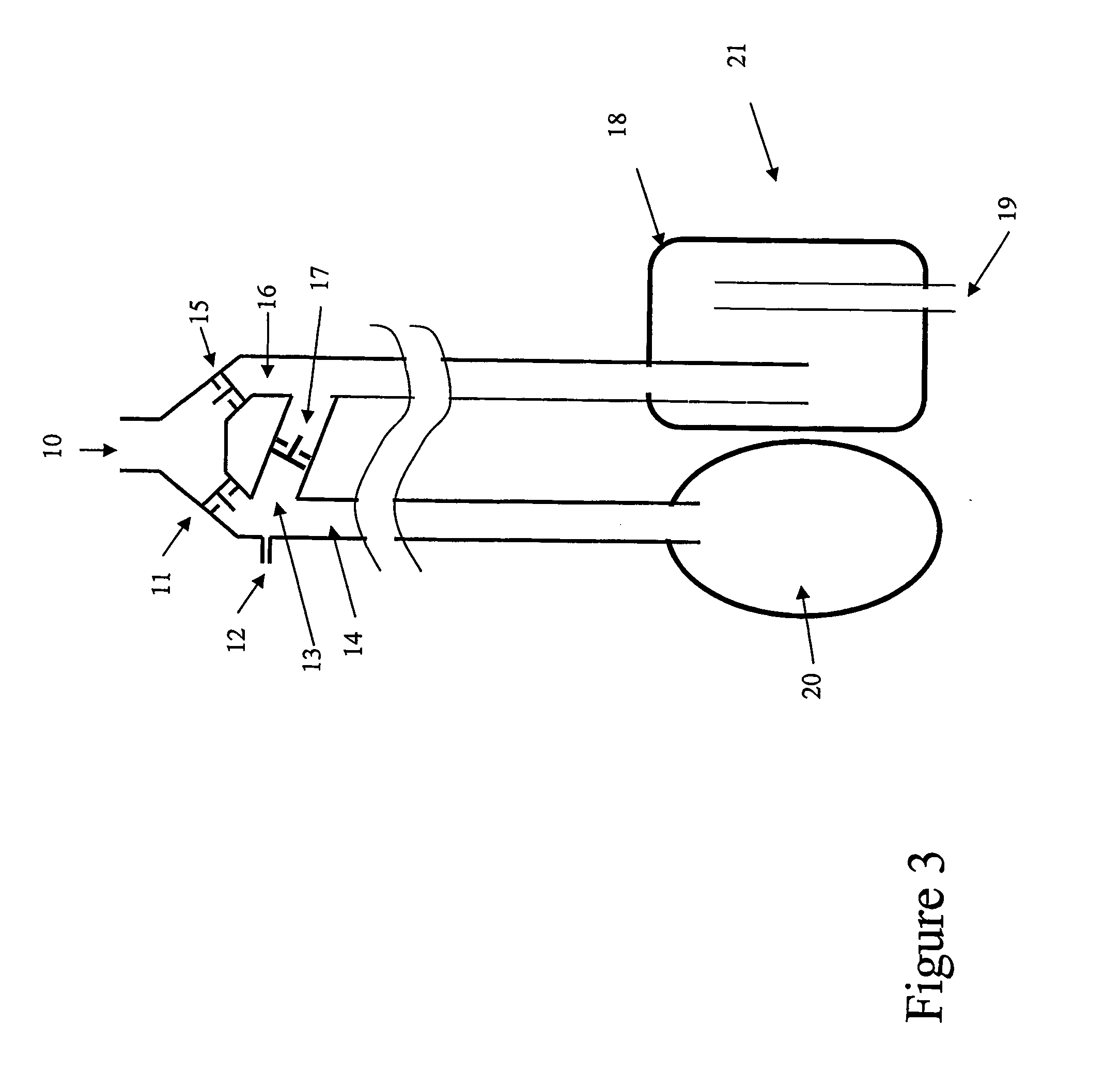
[0179] Referring now to Figure ??, an apparatus is shown with the following components: [0180] 1) a breathing circuit (202), said breathing circuit preferably has the characteristic that, on exhalation, exhaled gas is kept separate from inhaled gas and on inhalation, when {dot over (V)}E is greater than the flow of a first gas set (FGS) into the circuit, the subject inhales FGS gas first and then inhales a second gas set (SGS) gas, preferably said SGS containing CO2 and where SGS may be mostly previously exhaled gas. Any SGDB circuit can be used to greater or lesser benefit, according to its characteristics. We provide below detailed descriptions of several alternate configurations and outline their particular advantages and drawbacks with respect to measuring {dot over (Q)} and related parameters outlined above. [0181] 2) a gas sample line (204.1) leading to a gas analyzer (204) that monitors the concentration of gases, for example CO2, O2, at...


PUM


Abstract

An apparatus to measure cardiac output (Q) and other parameters such as alveolar ventilation (VA), minute CO2 elimination from the lung (VCO2 ), minute oxygen consumption (VO2), oxygenated mixed venous partial pressure of CO2, (PvCO2-oxy), true mixed venous partial pressure of CO2(PvCO2), PaCO2, mixed venous oxygen saturation (SvO2), pulmonary shunt, and anatomical dead space, consisting of: a) a breathing circuit with characteristics that: i. on exhalation, exhaled gas is kept substantially separate from inhaled gas; ii. oninhalation, when VE is greater than FGS flow, the subject inhales FGS first and then inhales a gas that is substantially SGS, for the balance of inhalation; b) gas sensor means for monitoring gas concentrations at the patient-circuit interface c) a first gas set (FGS), and a second gas set (SGS), said second gas set which may comprise previously exhaled gases or exogenous gases or both d) a gas flow control means for controlling the rate of FGS flow into the breathing circuit e) means to identify phase of breathing, said means may consist of pressure sensors or analysis of signal generated by gas sensors or other means known to those skilled in the art; f) machine intelligence consisting of a computer or logic circuit capable of controlling the gas flow control means, receiving the output of the gas sensor means and means to identify phased of breathing, and performing the calculations for measuring cardiac output and other parameters as outlined in the disclosure.

Description

FIELD OF THE INVENTION [0001] This invention discloses a method that calculates noninvasively, via the lung, the total cardiac output, pulmonary blood flow, shunt flow, anatomical and alveolar deadspace, true mixed venous O2 saturation, true mixed venous PCO2, and PaCO2. Furthermore the method can be performed in ventilated subjects, subjects breathing spontaneously, even in the presence of variations in their tidal volume and breathing frequency. Subjects need not perform any respiratory manoeuvre such as hyperventilation or breath holding to perform the test. BACKGROUND OF TE INVENTION [0002] 1. Importance of Cardiac Output [0003] A physician's ability to determine a patient's cardiac output ({dot over (Q)}, the volume of blood pumped by the heart each minute) is important in the assessment of critically ill patients. There are various devices and methods that provide a direct or indirect measure of {dot over (Q)} (see table 1). The most common method used in clinical practice is ...

Claims


Application Information

Patent Timeline
IPC IPC(8): F16K31/02A61M16/00A61B5/083A61M16/08A61M16/20A61M16/22
CPCA61B5/083A61M16/08A61M16/22A61M16/206A61B5/14551A61B5/7225A61B5/7278A61B5/0205A61M16/0833A61M16/085A61M16/0858A61M16/208A61M16/202A61M16/205
Inventor FISHER, JOSEPHPREISS, DAVIDAZAMI, TAKAFUMIVESELY, ALEXPRISMAN, ELTANSOMOGYI, RONNAYOT, DAN
Owner THORNHILL SCI INC
Why Eureka
Try Eureka