Method and apparatus for measurement of cardiopulmonary function

a cardiopulmonary function and measurement method technology, applied in the field of cardiopulmonary function measurement methods and apparatuses, can solve the problems of inability to use clinically, inability to accurately estimate the frc and pulmonary blood flow, and inability to use a technique that cannot be used clinically,

Active Publication Date: 2017-04-13
PHAN PHI ANH +2
View PDF1 Cites 4 Cited by
  • Summary
  • Abstract
  • Description
  • Claims
  • Application Information

AI Technical Summary

Benefits of technology

[0041]An advantage of this 3D surface approach is that it allows a robust estimation method (such as bisquare) to be used to remove outliers and to provide a confidence interval (e.g. a 95% confidence interval).
[0042]Thus, the method may further comprise steps such as maximum likelihood techniques to remove outliers from the estimated values of the alveolar volume VA and / or pulmonary blood flow {dot over (Q)}P, so as to give robust estimations of the alveolar volume VA and / or pulmonary blood flow {dot over (Q)}P, and corresponding confidence intervals (e.g. 95% confidence intervals).

Problems solved by technology

The use of the inspired sinewave technique has been previously investigated, but resulted in significant errors leading to incorrect results and a technique that could not be used clinically.
In particular, because of hardware limitations and rudimentary analytical techniques, the dead space recovered was over-estimated, which then resulted in an under-estimation of the FRC and pulmonary blood flow: estimated blood flow was 3 L / min compared to the expected 5.6 L / min for a male and 4.9 L / min for a female (Clifton et al., 2013 (two references)).
Steps to address robustness and outliers were also not described, which further added to the inaccuracy and low repeatability of the estimation of the FRC and pulmonary blood flow.
Accordingly, it was not possible to use the technique to provide a measurement of lung inhomogeneity.

Method used


Image

  • Method and apparatus for measurement of cardiopulmonary function
  • Method and apparatus for measurement of cardiopulmonary function
  • Method and apparatus for measurement of cardiopulmonary function

Examples


Embodiment Construction

Overview of the Inspired Sinewave Device

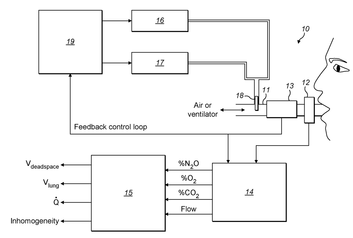
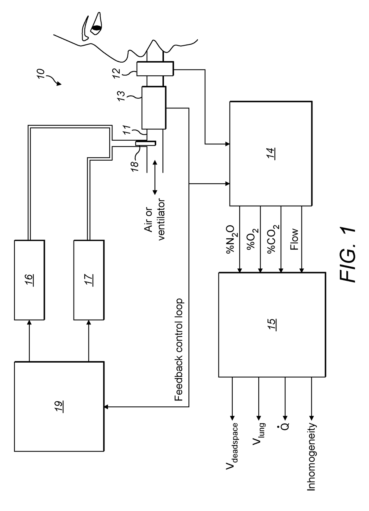
[0091]With reference to the figures, FIG. 1 provides an overview of the functional arrangement of an inspired sinewave device 10 according to an embodiment of the invention.

[0092]As illustrated, the inspired sinewave device 10 comprises a breathing tube 11, a mainstream gas analyser 12, a flow sensor 13, a data acquisition unit 14, a processing unit 15 configured to implement analysing algorithms, a N2O mass flow controller 16, an O2 mass flow controller 17, a mixing nozzle 18, and a controller 19.

[0093]In use, the patient breaths through the breathing tube 11 either by a mouthpiece or a face mask. The other end of breathing tube 11 is either connected to air (for spontaneous breathing patients) or to a ventilator (for ventilated patients). On this breathing tube 11, the mainstream gas analyser 12 is mounted to measure the concentration of N2O, and potentially of O2 and CO2 too. For example, infrared sensors can be used to measure N2O and CO2 ...


PUM


Abstract

A method for measuring anatomical dead space in a lung, the method comprising: (a) providing, in a supply of inspired gas, at least one indicator gas for inhalation by a patient during a test, the concentration of the indicator gas being controlled such as to follow a sinewave pattern over successive breaths; (b) measuring, over successive breaths, the flow rate and concentration of the indicator gas during both inspiration and exhalation of the patient; (c) fitting sinewave envelopes to the measured concentration values of the indicator gas over the successive breaths and, from the fitted sinewave envelopes, determining the inspired concentration, the mixed expired concentration, and the end expired concentration in respect of the indicator gas for each breath; and (d) calculating the anatomical dead space for each of a plurality of inspirations based on a conservation-of-mass principle. Also provided is a test apparatus for carrying out such a method, and a computer program or set of instruction code which, when executed, causes a processor to implement such a method.

Description

FIELD OF THE INVENTION[0001]The present invention relates to a method and associated apparatus for non-invasively measuring aspects of cardiopulmonary function in a subject. For example, embodiments of the invention may be used for non-invasively measuring one or more of anatomical dead space, functional residual capacity (FRC), pulmonary blood flow, and lung inhomogeneity.BACKGROUND TO THE INVENTION[0002]Dead space, functional residual capacity, pulmonary blood flow, and lung inhomogeneity are important parameters in relation to the cardiopulmonary condition of a patient. While there are methods available using respired gases to measure these parameters individually, it is currently difficult or even impossible to simultaneously give measurements of dead space, FRC, pulmonary blood flow, and lung inhomogeneity, and to make these measurements continuously.[0003]Dead space is the volume of air which is inhaled that does not take part in the gas exchange, either because it remains in ...

Claims


Application Information

Patent Timeline
Patent Type & Authority Applications(United States)
IPC IPC(8): A61B5/0205A61B5/00
CPCA61B5/0205A61B5/7235A61B5/7203A61B5/087A61B5/091A61B5/082A61B5/7221A61B5/08
Inventor PHAN, PHI ANHFARMERY, ANDREWHAHN, CLIVE
Owner PHAN PHI ANH
Why Eureka
Try Eureka