
Airborne radar monopulse front-view imaging method based on antenna directional diagram

An antenna pattern, airborne radar technology, applied in the field of radar, can solve problems such as image quality degradation, and achieve the effect of a robust method

Inactive Publication Date: 2016-05-25
XIDIAN UNIV
View PDF4 Cites 20 Cited by
  • Summary
  • Abstract
  • Description
  • Claims
  • Application Information

AI Technical Summary

Problems solved by technology

However, monopulse imaging is affected by the angle measurement technique, and when the actual antenna pattern does not match the ideal antenna pattern, the imaging quality degrades

Method used


Image

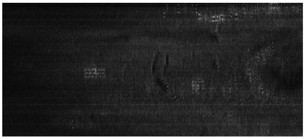
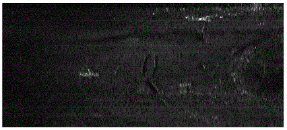
  • Airborne radar monopulse front-view imaging method based on antenna directional diagram
  • Airborne radar monopulse front-view imaging method based on antenna directional diagram
  • Airborne radar monopulse front-view imaging method based on antenna directional diagram

Examples


Embodiment Construction

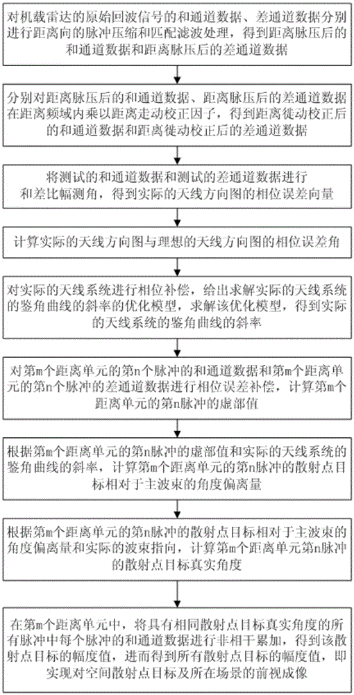
[0023] refer to figure 1 , a kind of airborne radar monopulse forward-looking imaging method based on antenna pattern of the present invention, comprises the following specific steps:

[0024] Step 1: Perform distance pulse compression and matched filter processing on the sum channel data and difference channel data of the original echo signal of the airborne radar, respectively, to obtain the sum channel data after the distance pulse pressure and the difference channel data after the distance pulse pressure .

[0025] Step 2: Multiply the sum channel data after the distance pulse pressure and the difference channel data after the distance pulse pressure by the distance walking correction factor H(f, t) in the distance frequency domain to obtain the sum channel data after distance migration correction and Difference channel data after distance migration correction.

[0026] The distance walk correction factor H (f, t), its expression is:

[0027] H ...


PUM


Abstract

The present invention discloses an airborne radar monopulse front-view imaging method based on antenna directional diagram. The method comprises the steps of (1) carrying out sum and difference amplitude angle measurement on tested sum channel data and tested difference channel data, (2) calculating the phase error angle of an actual antenna directional pattern and an ideal antenna directional pattern, (3) giving an optimization model for solving the slope K of the monopulse response curve of an actual antenna system, (4) calculating the scattering point target actual angle of the nth pulse of an mth distance unit according to the sum channel data and difference channel data of the nth pulse of the mth distance unit, (5) in the mth distance unit, carrying out non-coherent accumulation of the sum channel data of each pulse in all pulses with the same scattering point target actual angle, obtaining the amplitude value of a scattering point target, and thus obtaining the amplitude values of all scattering points, which means that the front-view imaging of a space scattering point target and the scene of the space scattering point target is realized.

Description

technical field [0001] The invention belongs to the technical field of radar, and in particular relates to an airborne radar monopulse forward-looking imaging method based on an antenna pattern, which can be used for ground reconnaissance and attack of aircraft, autonomous navigation, ocean search and terminal matching guidance of missiles. Background technique [0002] Airborne radar improves range resolution by transmitting a large time-width-bandwidth product signal, and improves azimuth resolution by using the Doppler bandwidth caused by the relative motion between the airborne platform and the ground target. Commonly used synthetic aperture radar ( SAR) and Doppler beam sharpening (DBS) technologies, etc., usually have the characteristics of all-day, all-weather, and high-resolution. However, when the radar works under the forward-looking condition, the aircraft track direction coincides with the antenna beam pointing, and the Doppler change rate of the echo signal is v...

Claims


Application Information

Patent Timeline
Patent Type & Authority Applications(China)
IPC IPC(8): G01S13/89
CPCG01S13/89
Inventor 李明陈洪猛王泽玉吴艳卢云龙闫永征张鹏左磊
Owner XIDIAN UNIV
Learn More