Crystalline color-conversion device

a color conversion device and crystal technology, applied in semiconductor laser excitation apparatus, lasers, semiconductor laser optical devices, etc., can solve the problems of high manufacturing cost, difficult to maintain pattern accuracy using metal shadow masks over large display substrates, and wasting much of the white light produced by back light, etc., to improve electrical efficiency, improve optical efficiency, and improve the effect of saturated colored ligh

Active Publication Date: 2018-01-16
X DISPLAY CO TECH LTD
View PDF267 Cites 26 Cited by
  • Summary
  • Abstract
  • Description
  • Claims
  • Application Information

AI Technical Summary

Benefits of technology

[0013]The present invention provides a light-emitting structure and display with improved optical efficiency, highly saturated colored light, and improved electrical efficiency. Embodiments of the present invention also enable robust methods of manufacturing.
[0015]Crystalline LEDs are efficient light emitters and direct-bandgap crystals efficiently absorb and transmit light. Closely locating the LED to the direct bandgap crystals provides an efficient, solid-state optical structure with few losses in an environmentally and mechanically robust device. Such a structure is also amenable to micro-transfer printing enabling an efficient and low-cost manufacturing method for display devices using the crystalline color-conversion device of the present invention.

Problems solved by technology

However, this approach has the disadvantage of wasting much of the white light produced by the back light.
However, it is difficult to maintain pattern accuracy using metal shadow masks over large display substrates, for example greater than 300 mm by 400 mm, or display substrates requiring high resolution.
However, the crystalline semiconductor layers also have a number of disadvantages.
For example, crystalline-based inorganic LEDs have high manufacturing costs, difficulty in combining multi-color output from the same chip, low efficiency, color variability and poor electrical current response.
However, this technique requires the use of different light emitters that emit different colors of light.
As noted above, different light emitters have different electrical and colorimetric properties leading to inefficiency and non-uniformity.
In general, color-change material systems suffer from efficiency problems.
For example, the production of relatively higher-frequency blue light can be difficult and the conversion of light from relatively higher frequencies to relatively lower frequencies may not be efficient.
Moreover, the conversion materials may fade over time, reducing the performance of the display.
Furthermore, much of the relatively higher-frequency light may not interact with the color-change materials and thus may not be converted to the desired, relatively lower frequency light.
However, the efficiency of emitted-light conversion remains a problem.
Because of the variability in LED materials and manufacturing processes, different LEDs, even when made in similar materials, will have different performances and losses in the circuits providing power to the different LEDs.
LEDs made in different materials have even greater inefficiencies when provided with a common power source.
Furthermore, these issues are exacerbated in LEDs since the variability of materials in a source semiconductor wafer is much greater on a smaller scale than on a larger scale.
These differences lead to performance inefficiency and uniformity variations.

Method used


Image

  • Crystalline color-conversion device
  • Crystalline color-conversion device
  • Crystalline color-conversion device

Examples


Embodiment Construction

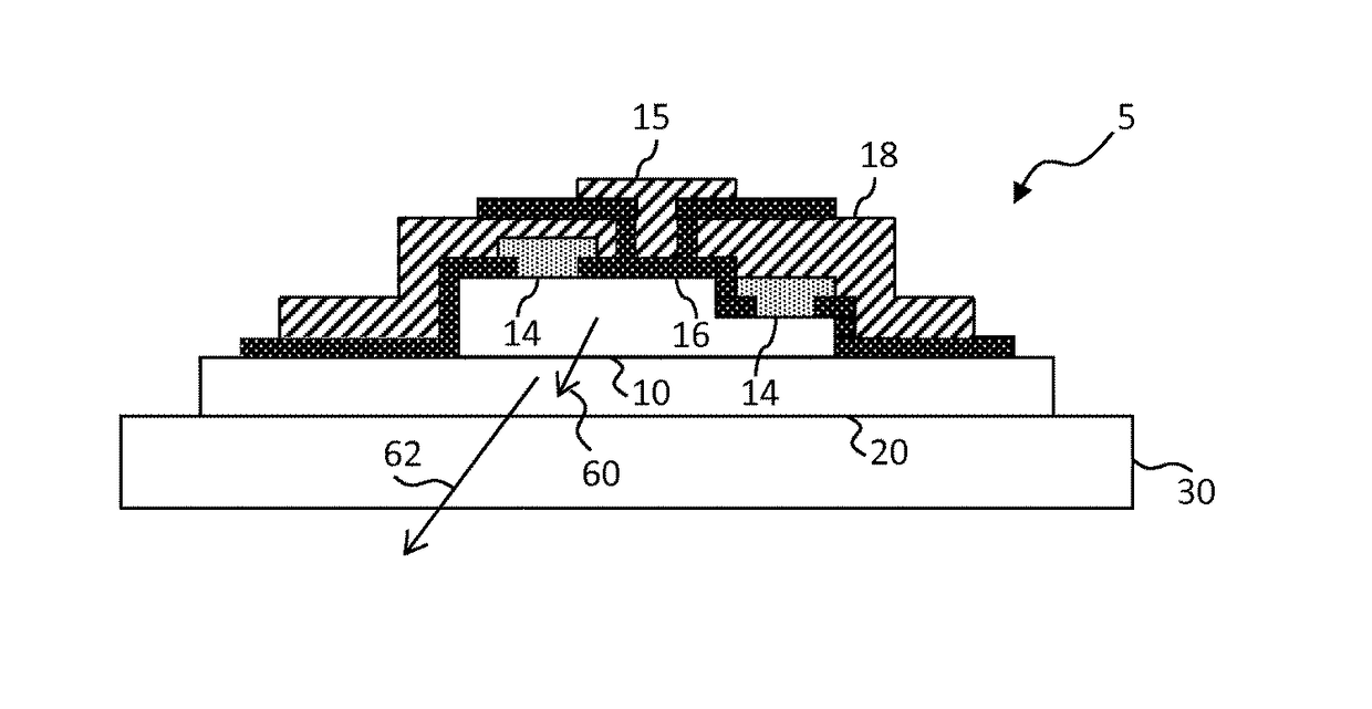
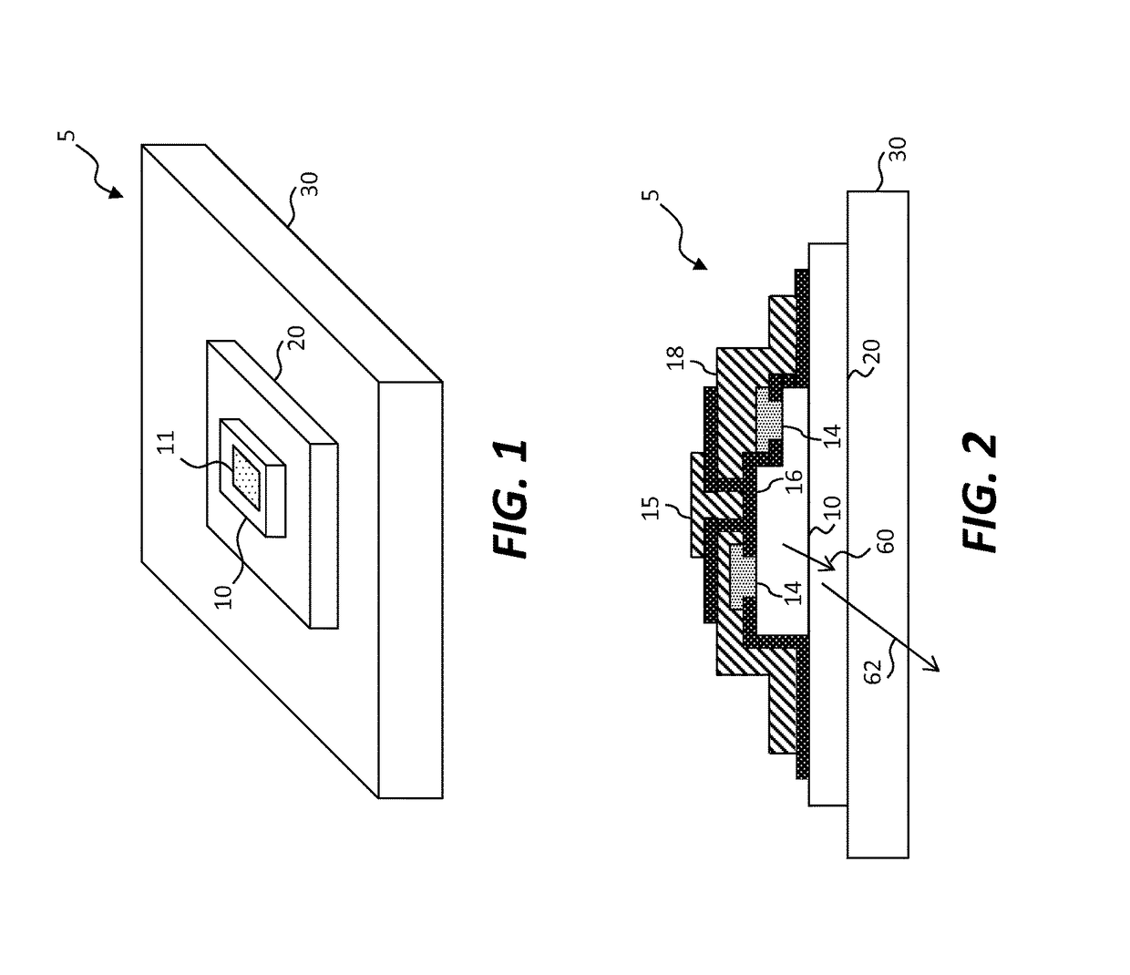
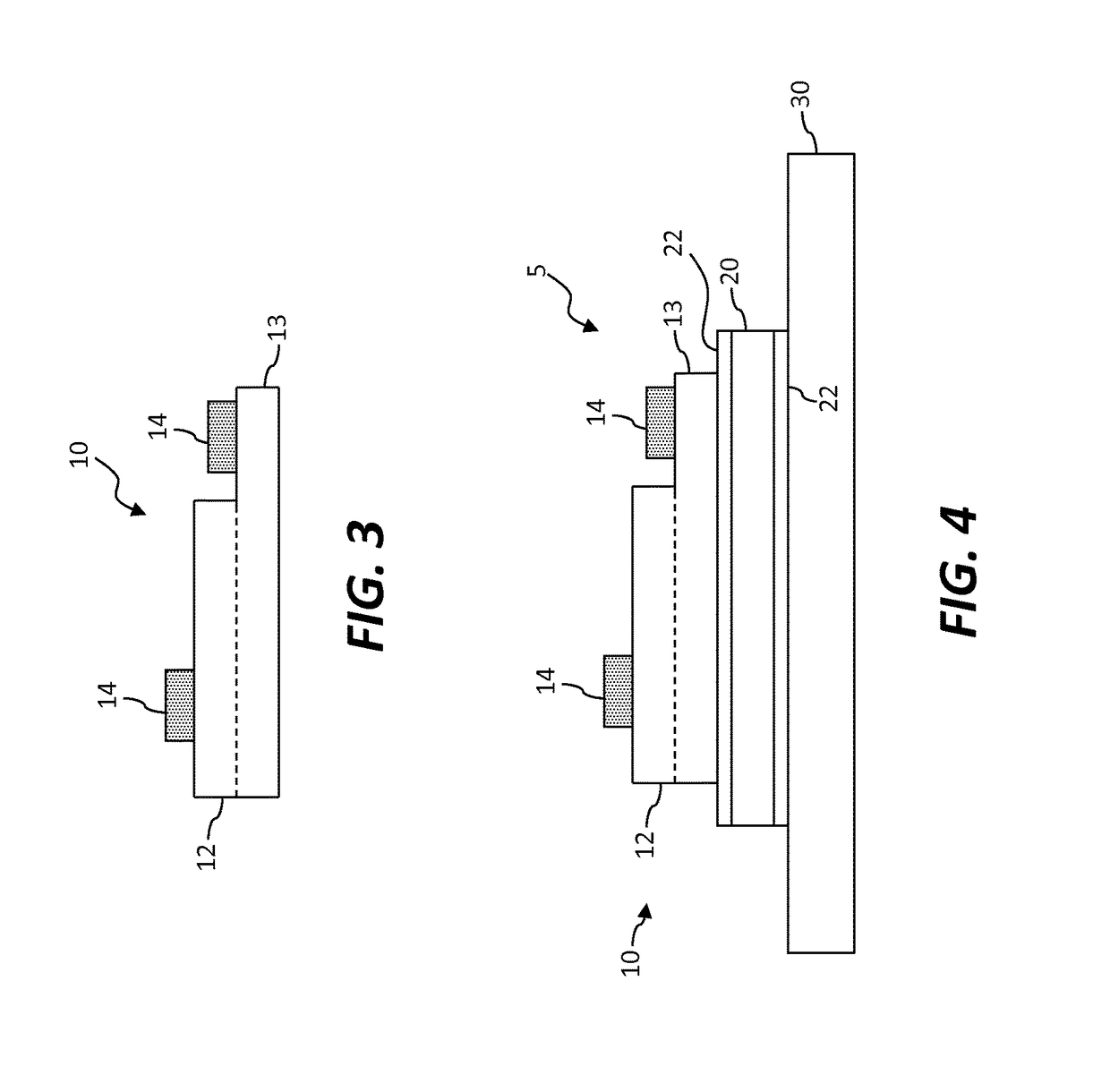
[0087]Referring to FIG. 1, in an embodiment of the present invention a crystalline color-conversion device 5 includes an electrically driven first light emitter 10 for emitting light having a first energy in response to an electrical signal, for example from a controller (not shown), from a light-emitting area 11 within the first light emitter 10. An inorganic solid single-crystal direct-bandgap second light emitter 20 having a bandgap of a second energy less than the first energy is electrically isolated from the first light emitter 10, is located in optical association with the first light emitter 10, and is located within 0 to 250 microns of the first light emitter 10 so that in response to the electrical signal the first light emitter 10 emits first light that is absorbed by the second light emitter 20 and the second light emitter 20 emits second light having a lower energy than the first energy.

[0088]As used herein, “in optical association” means that light from the first light...


PUM


Abstract

According to an embodiment, a crystalline color-conversion device includes an electrically driven first light emitter, for example a blue or ultraviolet LED, for emitting light having a first energy in response to an electrical signal. An inorganic solid single-crystal direct-bandgap second light emitter having a bandgap of a second energy less than the first energy is provided in association with the first light emitter. The second light emitter is electrically isolated from, located in optical association with, and physically connected to the first light emitter so that in response to the electrical signal the first light emitter emits first light that is absorbed by the second light emitter and the second light emitter emits second light having a lower energy than the first energy.

Description

PRIORITY APPLICATION[0001]This application claims priority to and the benefit of U.S. Provisional Patent Application No. 62 / 173,200, filed Jun. 9, 2015, titled “Crystalline Color-Conversion Device,” the content of which is incorporated by reference herein in its entirety.FIELD OF THE INVENTION[0002]The present invention relates to light-emitting structures using an electrically driven light emitter to optically pump an inorganic solid single-crystal direct-bandgap light emitter.BACKGROUND OF THE INVENTION[0003]Solid-state electrically controlled light emitters are widely used in the display and lighting industries. Displays often use differently colored emitters, and lighting applications require a large color rendering index (CRI). In either case, the efficient production of a variety of colors is important.[0004]Colored light is produced in liquid crystal displays (LCDs) and some organic light-emitting diode (OLED) displays using white-light emitters (such as a backlight) and colo...

Claims


Application Information

Patent Timeline
Patent Type & Authority Patents(United States)
IPC IPC(8): H01S5/04H01S5/00H01S5/40H01S3/0915H01S5/32H01S5/022H01S5/323
CPCH01S5/041H01S3/0915H01S5/005H01S5/32H01S5/4025H01S5/32341H01S5/02252H01S5/02276H01S5/02296H01L33/505H01L33/508H01L25/0753H01L33/507H01L33/502H01L2933/0041H01S5/02257H01S5/02326H01S5/02345
Inventor BOWER, CHRISTOPHERMEITL, MATTHEWCOK, RONALD S.
Owner X DISPLAY CO TECH LTD
Why Eureka
Try Eureka