Reversibly Deployable Spoiler

Active Publication Date: 2007-03-22
GM GLOBAL TECH OPERATIONS LLC
View PDF1 Cites 74 Cited by
  • Summary
  • Abstract
  • Description
  • Claims
  • Application Information

AI Technical Summary

Benefits of technology

[0008] Reversibly deployable spoilers and methods are disclosed herein. In one embodiment, the spoiler defines a surface of the vehicle that can increase or decrease airflow down force during movement of the vehicle. The spoiler comprises a housing having an opening; an airflow control member

Problems solved by technology

Vehicle lift and downforce can affect vehicle stability and handling.
Such devices generally do not adapt as driving conditions change, thus the airflow relative to the vehicle cannot be adjusted to better suit the changing driving conditions.
Vehicle designers are faced with the challenge of controlling the airflow while maintaining sufficient ground clearance to avoid contact with and damage by parking ramps, parking blocks, potholes, curbs and the like.
Further, inclement weather, such as deep snow slush or rainfall, can damage the device and/or impair vehicle handing.
The use of spoilers increase

Method used


Image

  • Reversibly Deployable Spoiler
  • Reversibly Deployable Spoiler
  • Reversibly Deployable Spoiler

Examples


Embodiment Construction

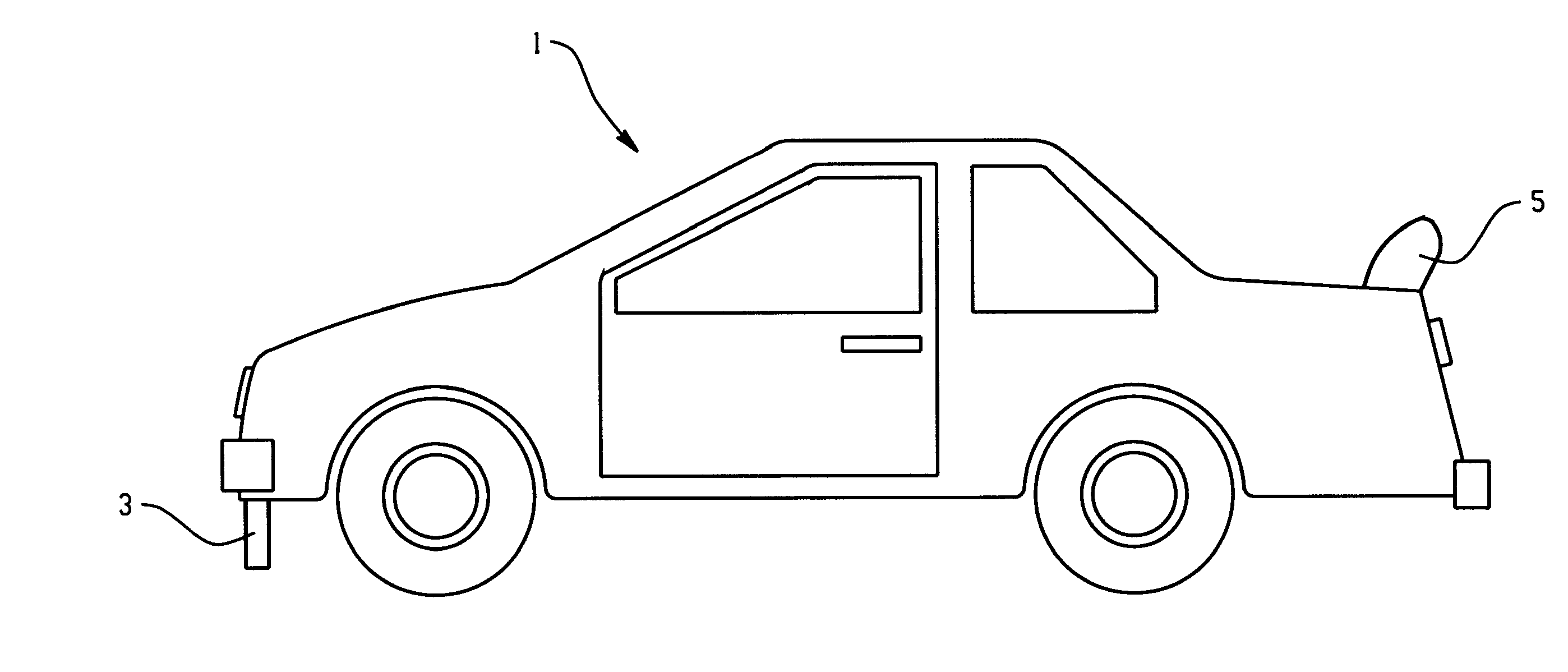
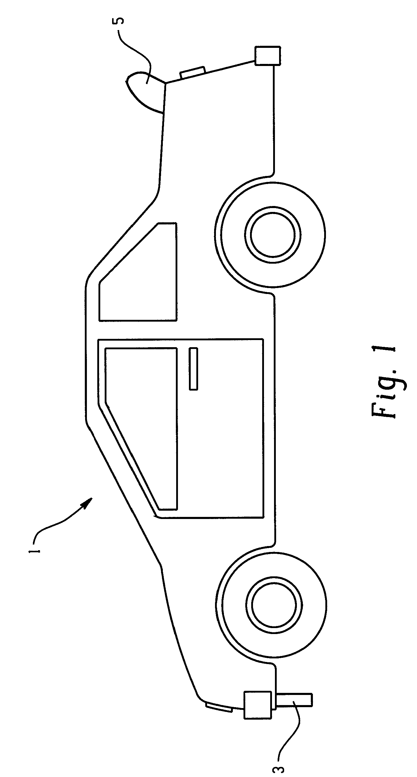
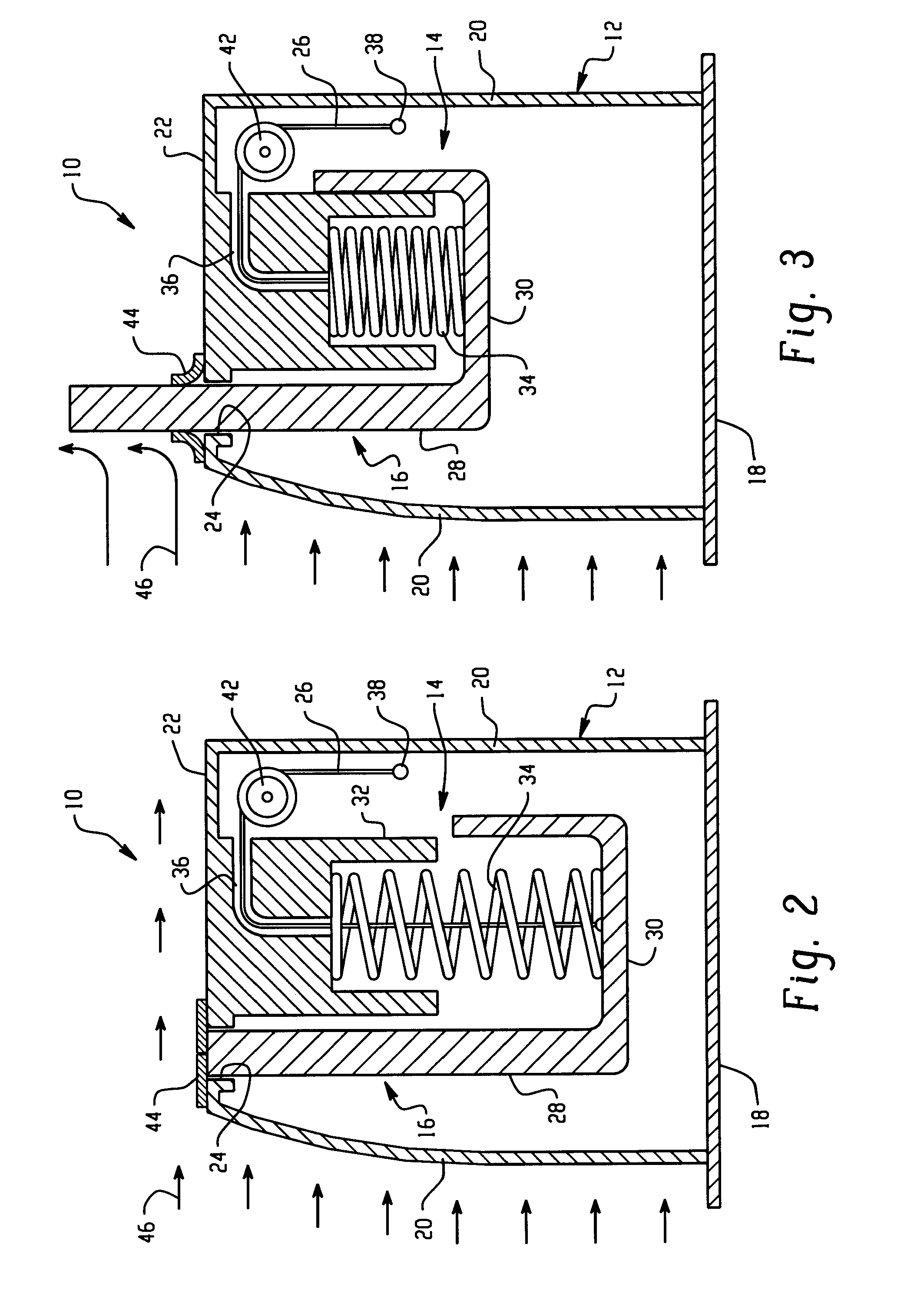
[0027] Active material actuated reversibly deployable airflow spoilers are disclosed herein. The airflow spoilers are suitable for use on vehicles on which it might be desirable to have on-demand greater downforce such as may be desired for vehicles utilized on occasion in competitive driving. It should be apparent that the airflow spoilers are mounted on a surface of the vehicle that can affect downforce to the vehicle during driving conditions. Typically, this position is at or about a rear deck of the vehicle although it is not intended to be limited to such location. Either deployment or stowing of the spoiler in these embodiments is in each case based on either a rigid body translation or rotation effected through just a single activation cycle (or at most a very small number of activation cycles) of an active material. Advantages associated with utilizing active materials to effect these changes include, among others, increased device simplicity, a reduced number of failure mo...


PUM


Abstract

A reversibly deployable spoiler for a vehicle comprises a body and an active material in operative communication with the body. The active material, such as shape memory material, is operative to change at least one attribute in response to an activation signal. The active material can change its shape, dimensions and/or stiffness producing a change in at least one feature of the active spoiler airflow control device such as shape, dimension, location, orientation, and/or stiffness to control vehicle airflow and downforce to better suit changes in driving conditions such as speed, while reducing maintenance and the level of failure modes. An activation device, controller and sensors may be employed to further control the change in at least one feature of the active spoiler airflow control device such as shape, dimension, location, orientation, and/or stiffness. A method for controlling vehicle airflow selectively introduces an activation signal to initiate a change of at least one feature of the device that can be reversed upon discontinuation of the activation signal.

Description

CROSS REFERENCE TO RELATED APPLICATIONS [0001] This application relates to and claims the benefit of priority to U.S. Provisional Patent Application No. 60 / 719,375 filed on Sep. 22, 2005, incorporated herein by reference in its entirety.BACKGROUND [0002] The present disclosure relates to airflow control devices for vehicles, and more particularly, to reversibly deployable vehicle spoilers that use active materials to effect deployment and retraction. [0003] Airflow over, under, around, and / or through a vehicle can affect many aspects of vehicle performance including vehicle drag, vehicle lift and down force, and cooling / heat exchange for a vehicle powertrain and air conditioning systems. Reductions in vehicle drag improve fuel economy. Vehicle lift and downforce can affect vehicle stability and handling. As used herein, the term “airflow” refers to the motion of air around and through parts of a vehicle relative to either the exterior surface of the vehicle or surfaces of elements o...

Claims


Application Information

Patent Timeline
IPC IPC(8): B62D35/00
CPCB62D35/00
Inventor BROWNE, ALAN L.JOHNSON, NANCY L.ROBER, KEVIN B.VOSS, MARK A.JUECHTER, TADGE J.MOSS, EDWARD D.
Owner GM GLOBAL TECH OPERATIONS LLC
Why Eureka
Try Eureka