
Apparatus and method for current control in h-bridge load drivers

Inactive Publication Date: 2007-03-22
MONUMENT PEAK VENTURES LLC
View PDF11 Cites 30 Cited by
  • Summary
  • Abstract
  • Description
  • Claims
  • Application Information

AI Technical Summary

Benefits of technology

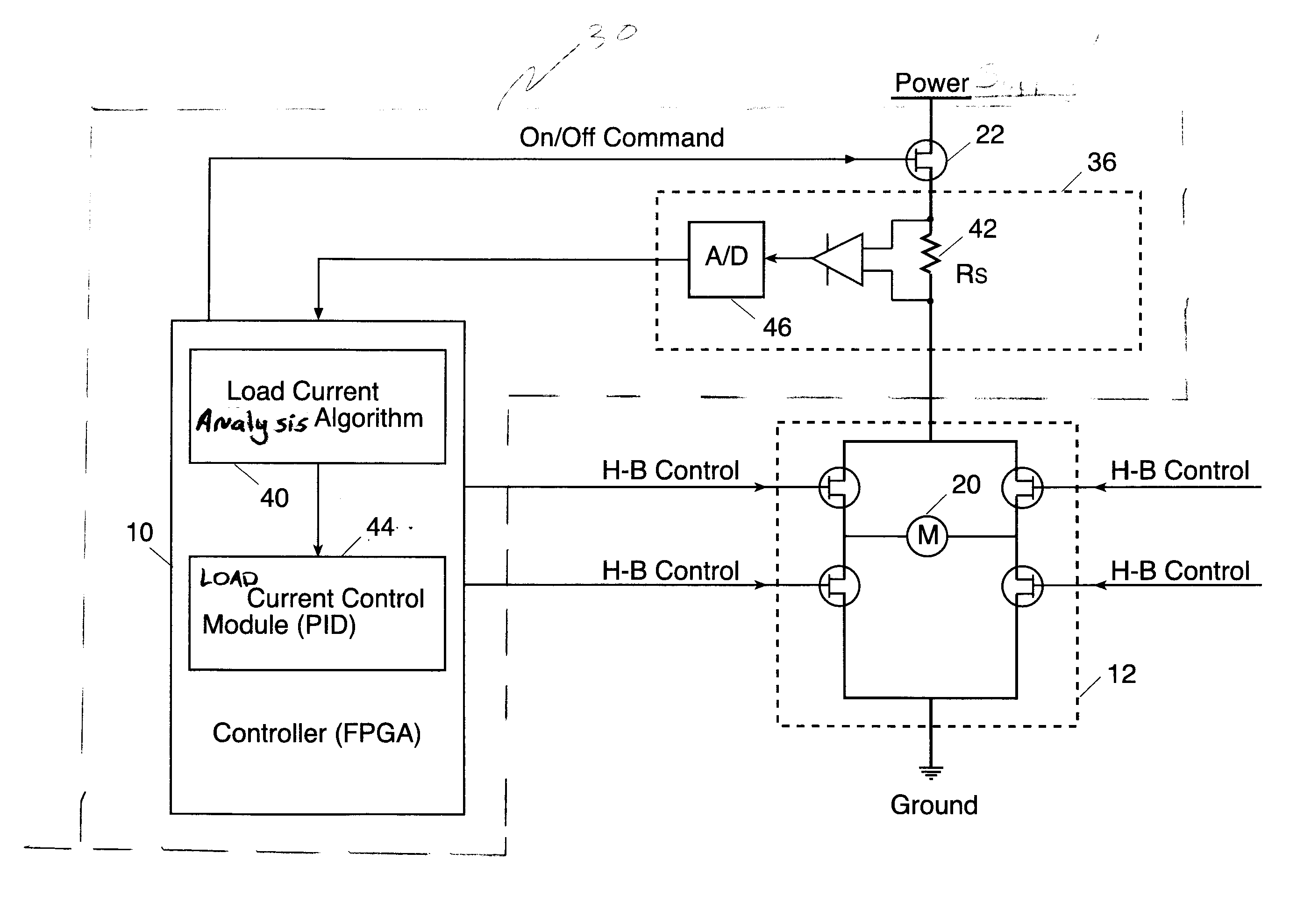
[0012] An electronic circuit of current control is provided. In one embodiment, this electronic circuit comprises a power-supply, an H-Bridge module connected to a load, and a current sensor connected between the H-Bridge module and the power-supply and adapted to sense load current characteristics. A computerized controller, connected to the current senso

Problems solved by technology

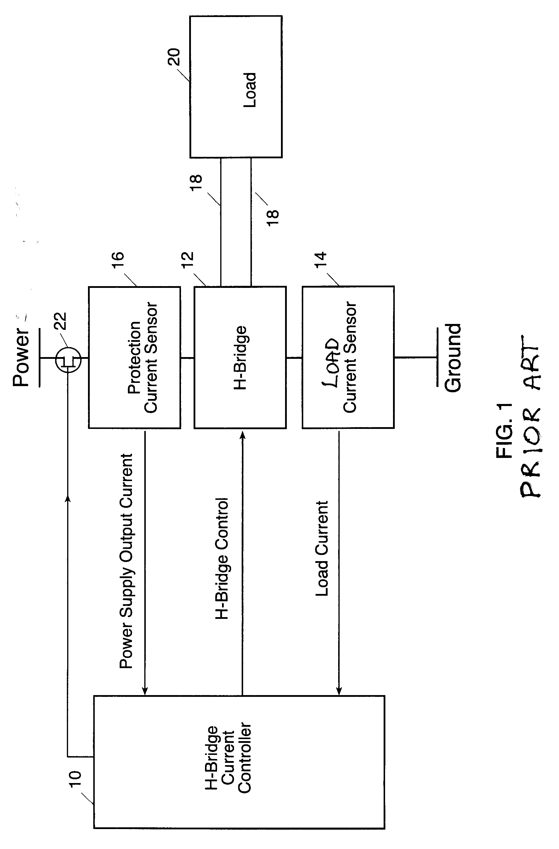
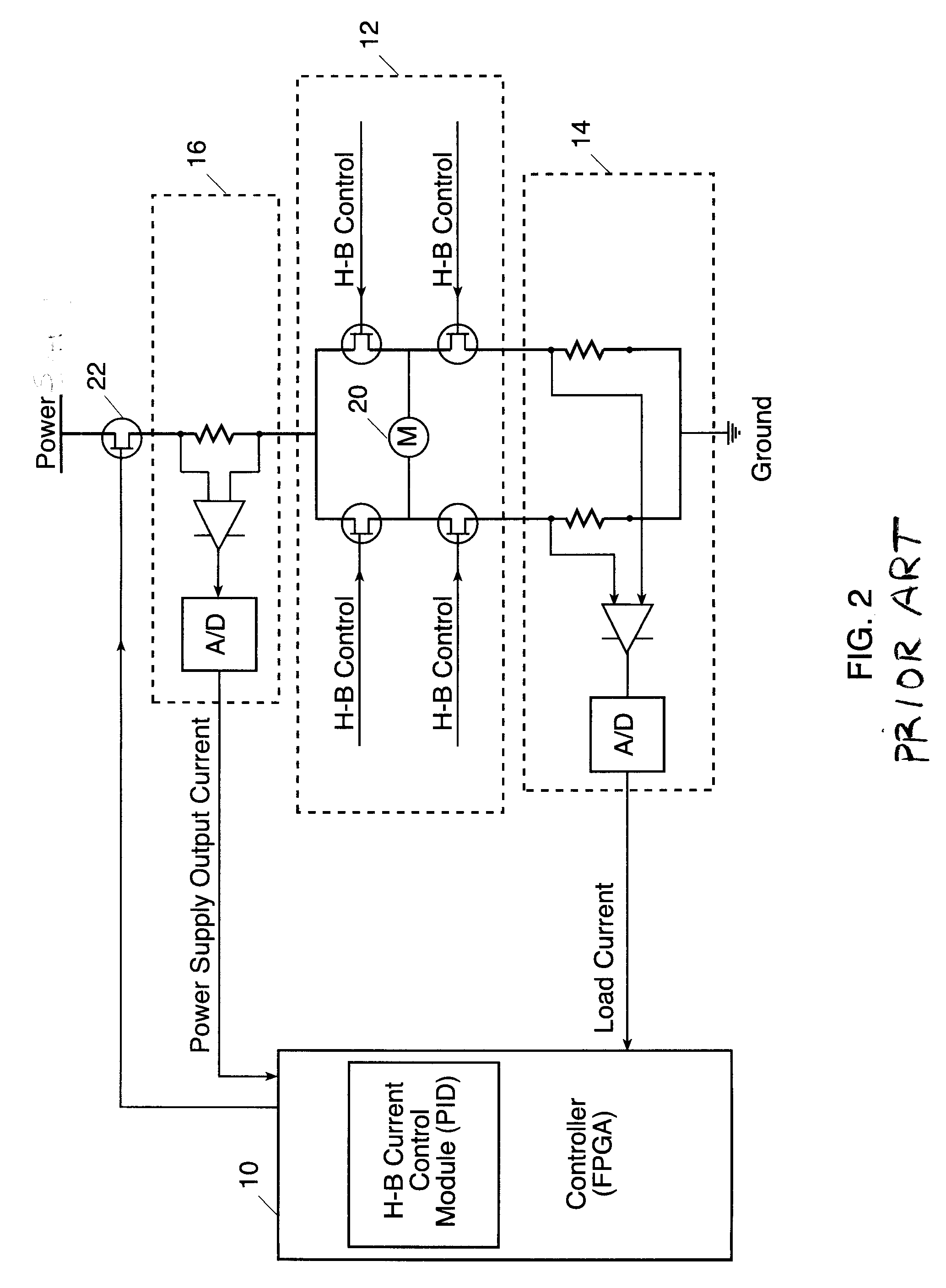
The multiplicity of output cells dictates a practical need to minimize the controller's complexity and size, especially in larger industrial systems, an issue having direct bearing on space, cost and reliability of the control device, especially in mass production.

Method used


Image

  • Apparatus and method for current control in h-bridge load drivers
  • Apparatus and method for current control in h-bridge load drivers
  • Apparatus and method for current control in h-bridge load drivers

Examples


Embodiment Construction

[0025] The described invention hereinafter relates to a novel method of current sensing and control as related to H-Bridge load drivers, useful in computerized electronic controller based systems.

[0026]FIG. 3 schematically illustrates one embodiment of a current control circuit 30. In this embodiment, current control circuit 30 comprises a single current sensor module 36, connected in the high-side of H-Bridge module 12 between a power supply 11 and H-Bridge module 12. As shown in FIG. 3, H-Bridge module 12 is connected to and drives a load 20. Current sensor module 36 senses current flow characteristics during the operation of H-Bridge module 12 of load 20. A signal representing the measured current is supplied to a computerized controller 32. Controller 32 receives the signal representing the measured current and a load current analysis algorithm module 40 that analyzes the sensed current characteristics to determine, by use of suitable algorithms, current control parameters that...


PUM


Abstract

An electronic current control circuit is provided. This electronic circuit comprises a power-supply, an H-Bridge module connected to a load, and a current sensor connected between the H-Bridge module and the power-supply and adapted to sense load current characteristics. A computerized controller is connected to the current sensor and the H-Bridge module, includes at least a module for operating load current analysis algorithm for analyzing the load current characteristics to determine current control parameters that provide over-current protection and load current control. A load current control module controls the H-Bridge module based upon the current control parameters.

Description

CROSS-REFERENCE TO RELATED APPLICATIONS [0001] This application claims priority from U.S. Provisional Application No. 60 / 719,447 entitled “The Use of Configurable Electronic Controller Technology in Vehicles” filed by Burkatovsky on 22 Sep. 2005. Further reference is made to commonly assigned, co-pending patent application U.S. Ser. No. (Attorney Docket No. 93085), entitled “Configurable Electronic Control System and Diagnostic Method”, filed concurrently herewith in the name of Siman-Tov.FIELD OF THE INVENTION [0002] The present invention relates to an improved load driver circuitry, particularly of the H-Bridge type, useful in industrial computerized automation and configurable electronic controllers. BACKGROUND OF THE INVENTION [0003] Electronic controllers are widely used in industrial automation and automotive applications, usually custom designed for specific groups of input sensors output devices and control applications. Configurable Electronic Controllers (CEC), as describe...

Claims


Application Information

Patent Timeline
IPC IPC(8): H02M7/5387
CPCH02H7/0838H02M3/157H02P7/29H02M2001/0009H02P7/0044H02M3/158H02P7/04H02M1/0009
Inventor SIMAN-TOV, ALON
Owner MONUMENT PEAK VENTURES LLC
Learn More