Interactive analysis and debugging of a circuit design during functional verification of the circuit design

a circuit design and functional verification technology, applied in the field of formal verification systems, can solve the problems of increasing complexity, consuming approximately 70-80% of the total time and resources, and increasing complexity of integrated circuits, so as to improve the practicality of formal verification and increase interactivity

Active Publication Date: 2009-03-17
JASPER DESIGN AUTOMATION
View PDF3 Cites 13 Cited by
  • Summary
  • Abstract
  • Description
  • Claims
  • Application Information

AI Technical Summary

Benefits of technology

[0010]A new use model for formal verification improves the practicality of formal verification, allowing for increased interactivity in the formal verification process. The new use model breaks down the generation of a formal proof into multiple steps and allows a user to provide insight about the design between steps through the manual analysis of the intermediate results. The model may also provide visual information to the user, further enabling the user to provide more useful feedback in the resolution process.

Problems solved by technology

Over the last 30 years, the complexity of integrated circuits has increased greatly.
This increase in complexity has exacerbated the difficulty of verifying circuit designs.
In a typical integrated circuit design process, which includes many steps, the verification step consumes approximately 70-80% of the total time and resources.
As a result, flaws in the design that are not found during the verification step can have significant economic impact by increasing time-to-market and reducing profit margins.
Circuit designers use high-level hardware description languages because of the size and complexity of modern integrated circuits.
Therefore, users typically let their formal verification tools run in a batch mode instead of interactively, frequently waiting overnight for the complex analysis to finish.
But the lack of interactivity leaves the designer's insights into the design out of the process, ultimately making the formal verification less effective.

Method used


Image

  • Interactive analysis and debugging of a circuit design during functional verification of the circuit design
  • Interactive analysis and debugging of a circuit design during functional verification of the circuit design
  • Interactive analysis and debugging of a circuit design during functional verification of the circuit design

Examples


Embodiment Construction

Overview

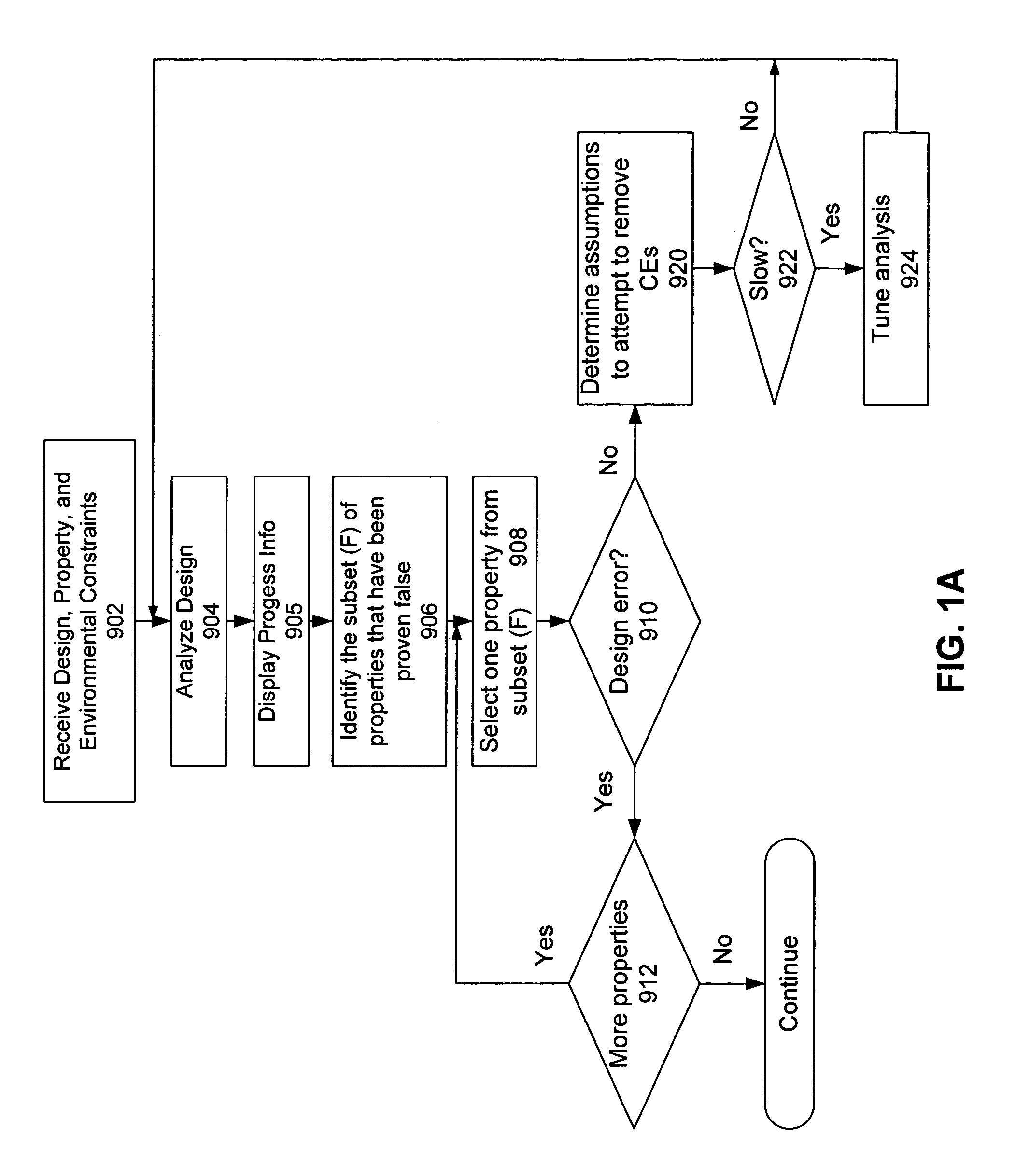
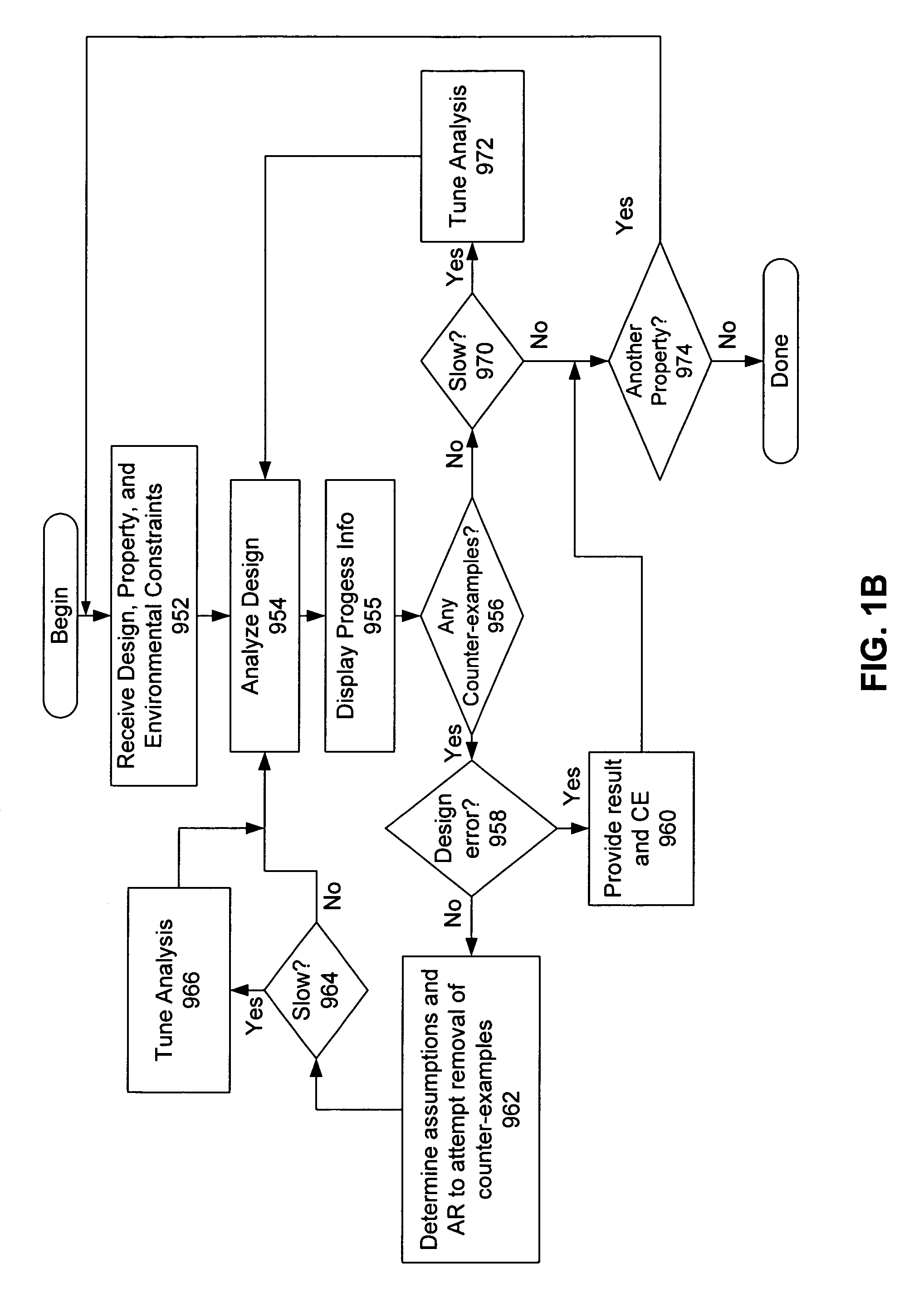
[0022]General approaches for resolving inconsistencies are illustrated in the flow charts of FIGS. 1A and 1B. The flow chart shown in FIG. 1A guides users to remove false negatives by providing feedback on the cost and effects of possible assumptions that are provided by the user or generated by the tool. FIG. 1B illustrates a similar process for guiding a user to remove false negatives, but the embodiment illustrated in FIG. 1B includes steps for dealing with methodologies that use the concept of an analysis region (AR).

[0023]With reference to FIG. 1A, a verification software suite (e.g., a “tool”) receives 902 a circuit design, a set of properties or requirements, and a set of environmental constraints for the functional verification process. The tool then analyzes 904 the circuit design to perform verification thereon. In one embodiment, this analysis includes a formal verification process as set forth in U.S. application Ser. No. 10 / 745,993, filed Dec. 24, 2003, which is...


PUM


Abstract

While performing functional verification on a circuit design, a verification tool allows a user to analyze the results of a previous functional analysis. The tool may also receive commands for a next verification analysis while performing a current analysis, and it may allow a user to abort a current analysis. Results from a completed analysis may be discarded or saved for viewing by a user while a next verification is performed on the circuit design. This allows a user to continue to debug and analyze the circuit design without having to wait until previous steps in the verification analysis are completed.

Description

CROSS REFERENCE TO RELATED APPLICATIONS[0001]This application claims the benefit of U.S. Provisional Application No. 60 / 556,782, filed Mar. 26, 2004, which is incorporated by reference in its entirety.BACKGROUND[0002]1. Field of the Invention[0003]This invention relates generally to the field of functional verification of digital designs, and in particular to formal verification systems that involve building a formal test bench to rely on user interactivity rather than full automation.[0004]2. Background of the Invention[0005]Over the last 30 years, the complexity of integrated circuits has increased greatly. This increase in complexity has exacerbated the difficulty of verifying circuit designs. In a typical integrated circuit design process, which includes many steps, the verification step consumes approximately 70-80% of the total time and resources. Aspects of the circuit design such as time-to-market and profit margin greatly depend on the verification step. As a result, flaws ...

Claims


Application Information

Patent Timeline
Patent Type & Authority Patents(United States)
IPC IPC(8): G06F17/50G06F9/45
CPCG06F17/504G06F30/3323
Inventor IP, CHUNG-WAH NORRISJAIN, MOHIT KUMAR
Owner JASPER DESIGN AUTOMATION
Why Eureka
Try Eureka