
Method for monitoring packet loss ratio

Inactive Publication Date: 2007-03-22
HUAWEI TECH CO LTD
View PDF4 Cites 30 Cited by
  • Summary
  • Abstract
  • Description
  • Claims
  • Application Information

AI Technical Summary

Benefits of technology

[0005] The present invention provides a method for monitoring packet loss ratio in a label switching network, by which the accurate packet loss ratio of a label switching path (LSP) of the label switching network can be obtained in time.
[0014] It can be seen from the above description that, in the method according to the present invention, the packet statistical information obtained by the source node of the LSP is sent to the destination node through the extended OAM frames, which includes: a newly defined OAM frame used for monitoring the packet loss ratio, a CV frame or an FFD frame, therefore, the destination node can obtain the packet statistical information from the upstream node and calculate the packet loss ratio in time. This method has such advantages as that the packet loss ratio can be obtained in time, the packet loss ratio calculated is accurate, and the method is simple to realize. Moreover, by the method according to the present invention, network resources, such as bandwidth, occupied by sending the packet statistical information of the label switching network are greatly reduced.
[0015] Furthermore, the present invention also provides a method for monitoring the packet loss ratio in the multi-domain label switching network, by which the packet loss ratio of an LSP segment in one OAM domain can be monitored, thus the performance and security of each part of the label switching network can be determined expediently, and the part responsible for deterioration of the performance of the network can be located.

Problems solved by technology

Since the packet loss ratio is an important index indicating the performance of a network, and it can reflect the quality of service (QoS) of the network, how to monitor the packet loss ratio in a label switching network becomes an urgent problem to be solved.

Method used


Image

  • Method for monitoring packet loss ratio
  • Method for monitoring packet loss ratio
  • Method for monitoring packet loss ratio

Examples


first embodiment

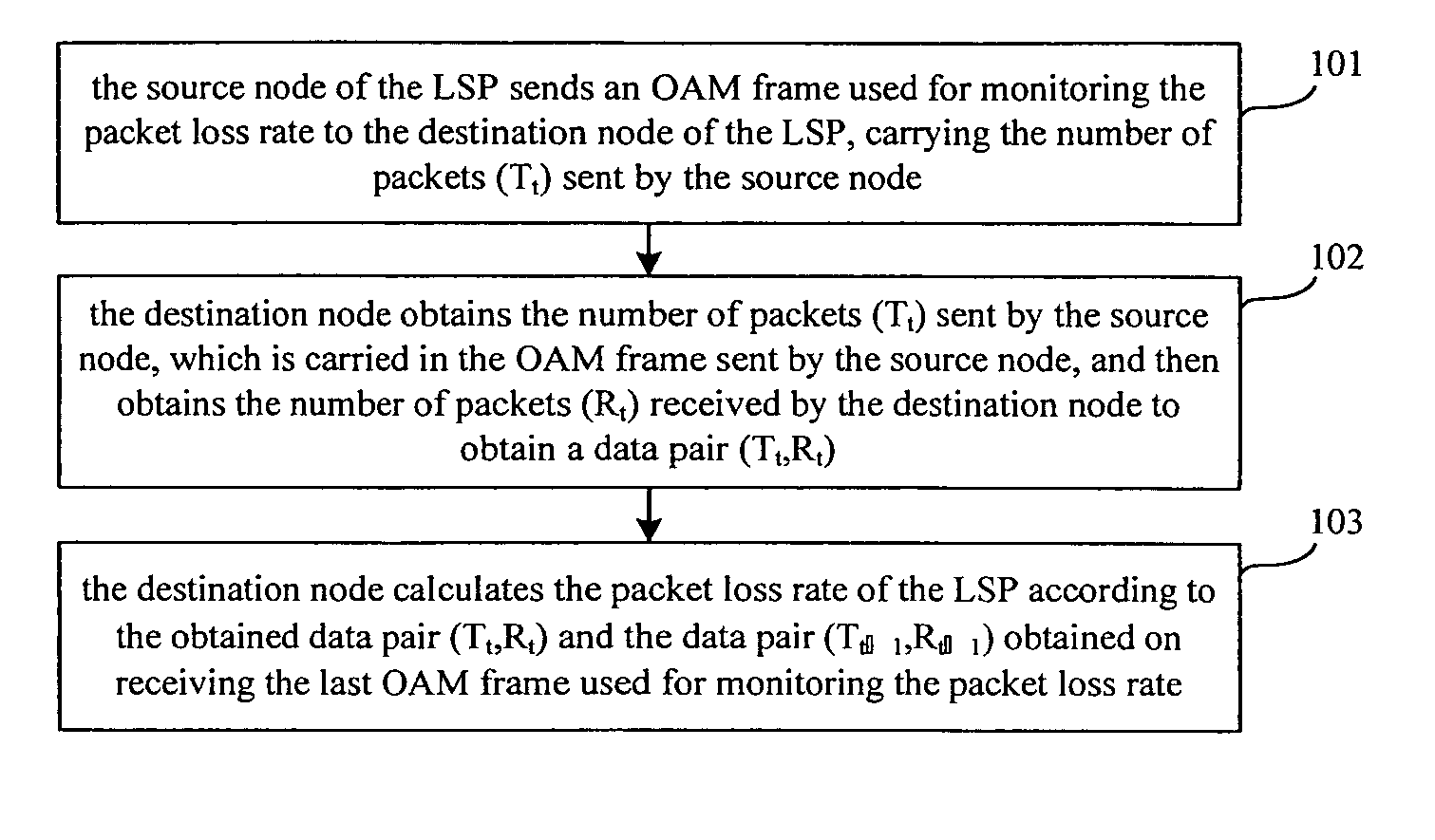
[0022] In the method according to the present embodiment, the existing OAM frame is extended to carry packet statistical information. The specific extending method includes the following steps: A new OAM type is defined to identify the OAM frame used for monitoring the packet loss ratio. The newly defined OAM frame used for monitoring the packet loss ratio is uniquely identified by the newly defined OAM type in the type field of the existing OAM frame. Another field of the OAM frame type is defined as a packet statistic field to carry the packet statistical information. According to the present embodiment, the packet statistical information refers to the number of packets sent by the source node of the LSP.

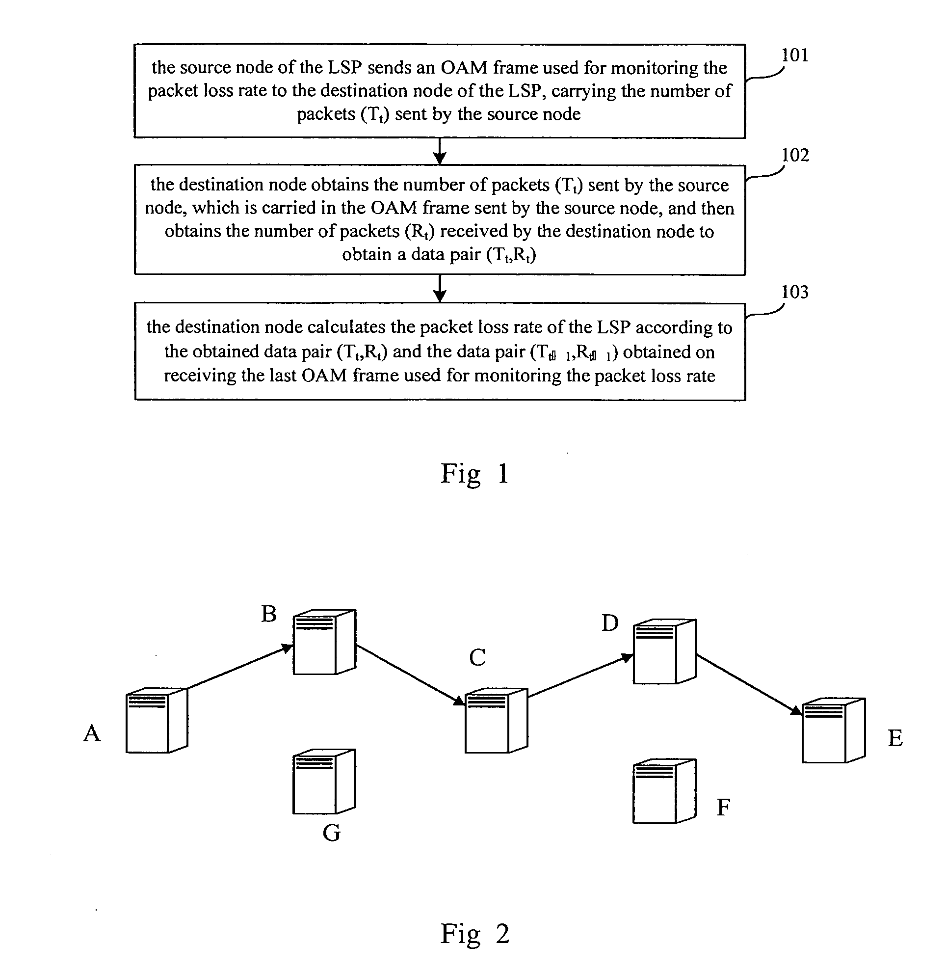
[0023]FIG. 1 is the flow chart of the method for monitoring the packet loss ratio via the extended OAM frame. As shown in FIG. 1, the method mainly includes the following steps.

[0024] Step 101: the source node of the LSP sends an OAM frame used for monitoring the packet loss rati...

second embodiment

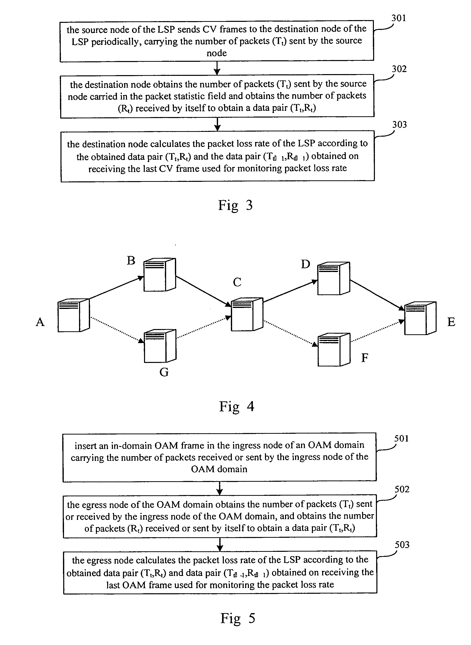
[0032] Besides the method of extending the existing OAM frame, other types of OAM frame can also be used for monitoring the packet loss ratio. the present invention provides a method of carrying the packet statistical information by an existing Connectivity Verification (CV) frame or Fast Failure Detection (FFD) frame used as the OAM frame.

[0033] In the label switching network, in order to detect the state of a created LSP, the source node of the LSP will send a CV frame or FFD frame to the destination node periodically, and the destination node will determine if the LSP is normal or not according to whether the CV frame or FFD frame sent by the source node are received periodically. The time interval for the source node sending the CV frames or FFD frames can be from several micro seconds (ms) to several seconds (s). For example, for FFD frames, the minimum sending time interval can be 10 ms. Therefore, the source node can utilize the CV frames or FFD frames to transmit the packet ...

third embodiment

[0045] the present invention provides a method for monitoring the packet loss ratio of each OAM domain of an LSP in the case that the LSP is a multi-domain LSP.

[0046] While performing distributed domain management to an LSP, one or a plurality of OAM domain(s) will be pre-appointed in the LSP, at the same time an ingress node and an egress node of each OAM domain are determined. The OAM domains can be consistent with the routing domains of the LSP. In this case, the OAM domains are automatically created when the routing domains are created. Alternatively, the OAM domains can be inconsistent with the routing domains. In this case, the OAM domains and the ingress and egress nodes thereof can be appointed via configuration.

[0047] As shown in FIG. 4, nodes A, B, C and G of the label switching network constitute one OAM domain, wherein node A is the ingress node and node C is the egress node of this OAM domain, LSP A→B→C is a working LSP, and LSP A→G→C is a protection LSP. Meanwhile nod...


PUM


Abstract

A method of monitoring the packet loss ratio in a label switching network is disclosed, in which an OAM frame carrying packet statistical information used for monitoring the packet loss ratio is sent by the source node to the destination node of an LSP such that the current packet loss ratio could be calculated upon receiving the OAM frame by the destination node according to the packet statistical information. The present invention also discloses a method for monitoring the packet loss ratio in a multi-domain label switching network. By the method for monitoring the packet loss ratio described in the present invention, the packet loss ratio can be monitored and obtained timely and accurately. The method is simple to realize while few modifications have to be made on the existing label switching network.

Description

CROSS-REFERENCE TO RELATED APPLICATIONS [0001] This application is a continuation application of International Application No. PCT / CN2006 / 000534, filed Mar. 29, 2006, which claims priority in Chinese Application No. 2005-10058846.1, filed Mar. 30, 2005, both of which are entitled “Method for Monitoring Packet Loss Ratio”. The full disclosure of these applications are hereby incorporated by reference. FIELD OF THE INVENTION [0002] The present invention relates to label switching technology, and more particularly, to a method for monitoring packet loss ratio in a label switching network or in a multi-domain label switching network. BACKGROUND OF THE INVENTION [0003] As a key technique of Next Generation Network (NGN), Multi-Protocol Label Switching (MPLS) technique has become more and more important in an Internet Protocol (IP) network. At present, the MPLS technique has evolved into General MPLS (GMPLS) through further alteration, and GMPLS can be used in a packet switching network s...

Claims


Application Information

Patent Timeline
IPC IPC(8): H04L12/26
CPCH04L41/142H04L43/0829H04L45/50
Inventor HE, JIANFEI
Owner HUAWEI TECH CO LTD
Learn More