Transmission apparatus with function of multi-step bandwidth assignment to other communication apparatuses

a communication apparatus and multi-step technology, applied in the field of transmission apparatus, can solve the problems of unstable cbr (constant bit rate) communication, and erroneous use of fixed bandwidth resources, so as to prevent variable bandwidth control from affecting fixed bandwidth control, flexible bandwidth control is achieved, and the effect of preventing the fluctuation of data arrival delay tim

Inactive Publication Date: 2007-03-22
HITACHI LTD
View PDF9 Cites 59 Cited by
  • Summary
  • Abstract
  • Description
  • Claims
  • Application Information

AI Technical Summary

Benefits of technology

[0017] To achieve the control described above, the bandwidth controller prepares a fixed bandwidth configuration table separate from a variable bandwidth configuration table, thus separating control of one type of traffic from control of another and preventing variable bandwidth control from affecting fixed bandwidth control. This also makes it possible to set assignment cycles for fixed bandwidth control and variable bandwidth control individually, and more flexible bandwidth control is attained.
[0018] This invention prevents data arrival delay time from fluctuating by preferentially securing fixed transmission timing and transmission bandwidth for data that is requested to be sent in r...

Problems solved by technology

In the case where a single bandwidth configuration table handles fixed bandwidth data and variable bandwidth data, variable bandwidth data affects fixed bandwidth data, which makes it difficult to assign a bandwidth to fixed bandwidth data dynamically and results in unstable CBR (Constant Bit Rate) communications where the bit rate is constant.
Specifically, treating every traffic the same means that the utilization state of variable bandwidth is checked not only in variable bandwidth assignment but also in fixed bandwidth assignment and there is a possibility that a resource secured or to be secured for fixed bandwidth data is erroneously used for transmission o...

Method used


Image

  • Transmission apparatus with function of multi-step bandwidth assignment to other communication apparatuses
  • Transmission apparatus with function of multi-step bandwidth assignment to other communication apparatuses
  • Transmission apparatus with function of multi-step bandwidth assignment to other communication apparatuses

Examples


Embodiment Construction

[0039] This invention relates to a bandwidth assignment method, and is irrespective of whether an optical signal or an electric signal is used as a transmission medium in a physical layer of an OSI reference model. However, this specification describes as the best mode of carrying out this invention a bandwidth assignment method and apparatus in a PON system employed for user access lines.

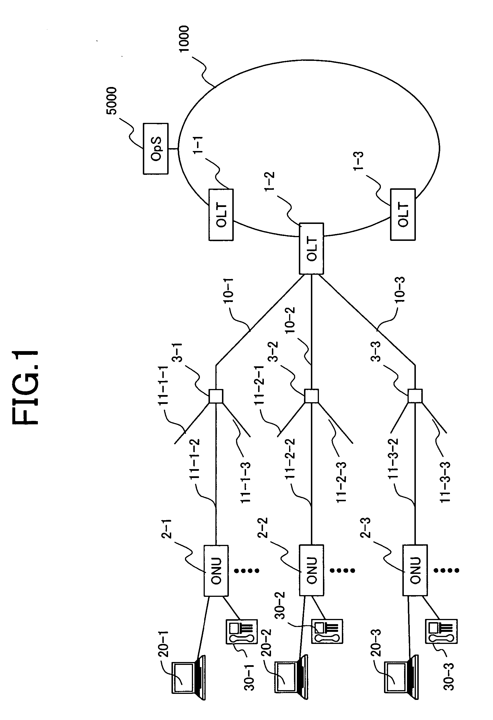
[0040]FIG. 1 is a block diagram showing a configuration of a subscriber termination network that is built from a PON system as an embodiment of this invention.

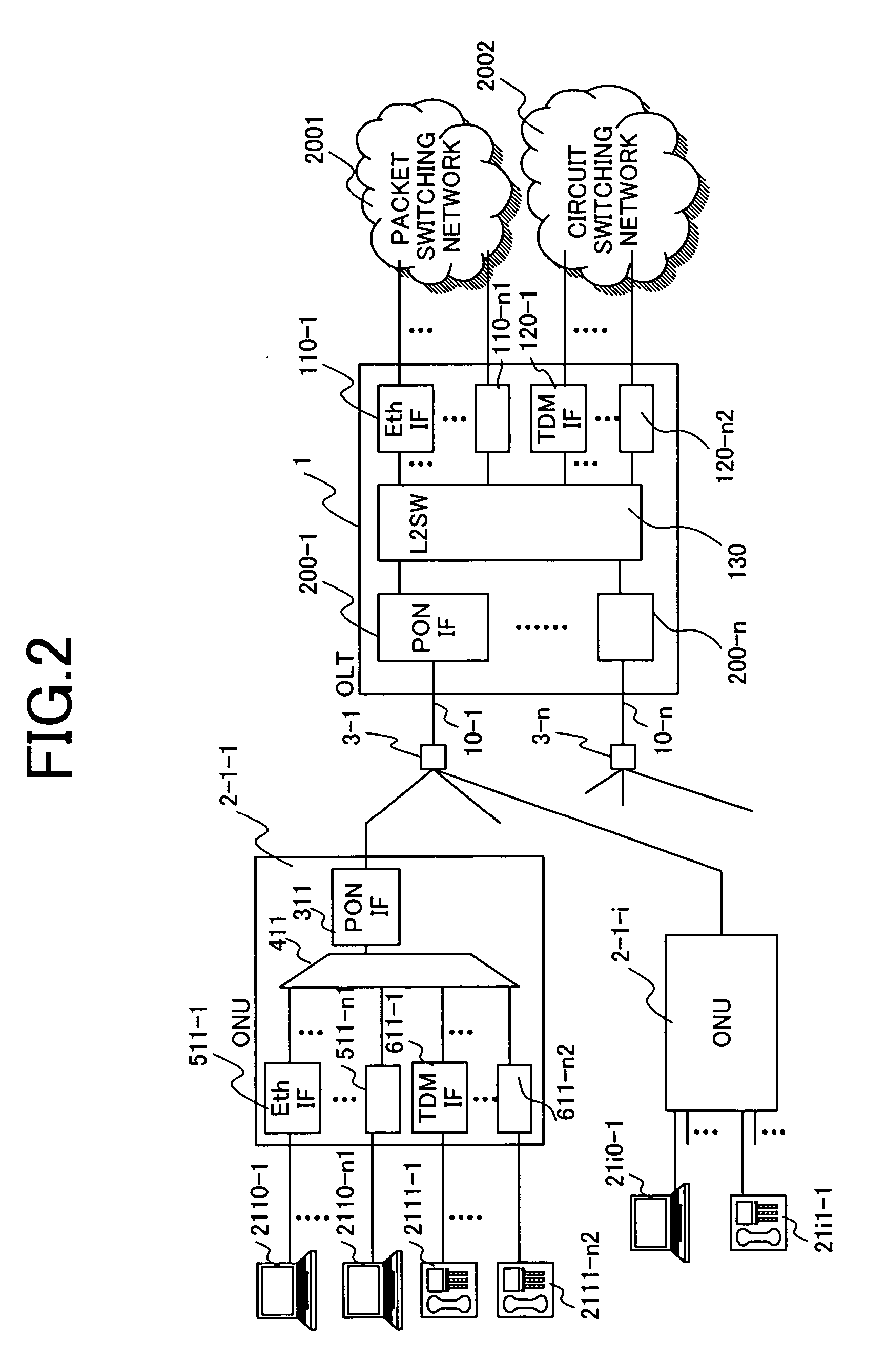
[0041] This network has Optical Line Terminals (OLTs) 1-1 to 1-3, Optical Network Units (ONUs) 2-1 to 2-3, optical splitters 3-1 to 3-3, and optical fibers 10-1 to 10-3 and 11-1-1 to 11-3-3. The plural OLTs 1-1 to 1-3 are placed at the edge of a network containing user lines, and each OLT houses plural ONUs. The OLTs 1-1 to 1-3 each have plural PON-IFs as shown in FIG. 2. For example, the OLT 1-2 is connected to the ONU 2-1 via the optical ...


PUM


Abstract

A transmission apparatus for use in fixed bandwidth communications and variable bandwidth communications. The transmission apparatus has a memory unit, which stores information contained in a frame and indicating the amount of data to be transmitted from a terminal device, a computing unit, which calculates a bandwidth amount to be assigned to the terminal device based on the data amount, and a transmission unit, which sends the calculated assigned bandwidth amount to the terminal device. The transmission apparatus is characterized in that the computing unit calculates bandwidth amounts to be assigned to different types of flow of which different transmission qualities are requested according to a priority level that is set to each flow type. The transmission apparatus is also characterized in that bandwidth is controlled by designating, instead of a necessary bandwidth amount, transmission starting timing and transmission ending timing, particularly for fixed bandwidth communication data.

Description

CLAIM OF PRIORITY [0001] The present application claims priority from Japanese patent application P2005-257905 filed on Sep. 6, 2005, the content of which is hereby incorporated by reference into this application. BACKGROUND OF THE INVENTION [0002] This invention relates to a transmission apparatus that sends and receives data divided into frames or packets, and more particularly to a bandwidth director used in a transmission apparatus that is connected physically or logically to plural terminal devices and houses multiplexed connections with the terminal devices to control the amount of data transmitted to the individual terminal devices. More specifically, this invention relates to a line termination device that is a subscriber line termination device for providing a connection line from a user's house, an office building, or a housing complex to a carrier's central office housing user lines, and that employs wavelength-division multiplexing or time-division multiplexing to multip...

Claims


Application Information

Patent Timeline
IPC IPC(8): H04J3/22H04L12/44H04L12/801H04L12/851H04L12/911
CPCH04L12/5695H04L47/10H04L47/15H04L47/2433H04L47/805H04L47/30H04L47/365H04L47/788H04L47/263H04L47/70
Inventor MIZUTANI, MASAHIKOASHI, YOSHIHIROTAKASE, MASAYUKISAKAMOTO, KENICHIIWAMURA, ATSUSHIKAZAWA, TOHRUSAKAMOTO, NORIHIRO
Owner HITACHI LTD
Why Eureka
Try Eureka