Debris shield for a rotary tool or machine

a technology of rotary tools and shields, which is applied in the field of rotary tools or machines, can solve the problems of preventing the efficient evacuation of the boot on a continuous basis, providing no air intake facilities, and not providing for the accommodation of different types and sizes of tools

Active Publication Date: 2007-03-22
SKRADSKI THOMAS J
View PDF21 Cites 44 Cited by
  • Summary
  • Abstract
  • Description
  • Claims
  • Application Information

AI Technical Summary

Benefits of technology

[0007] The present invention provides a debris shield for a rotary tool that rotates a surface working implement such as a drill, spade bit, hole saw or sanding disc, and that generates debris while working on a surface, such as by sanding or cutting or drilling holes in a floor, wall or ceiling. The debris shield of the invention eliminates the need for the worker to use a protective dust mask or eye protection, and greatly reduces the need for work area preparation and clean-up normally required before and after cutting or drilling.
[0010] In all versions of the debris shield of the invention, the bottom of the of the debris collection housing is preferably provided with a surface contact rim having an inner ring wall which angles inwardly from the ring's bottom contact surface to provide a dust pan effect in capturing debris produced by the drilling or cutting operation. This surface contact rim can be a separate element made of a resilient material, and can be fitted onto the bottom edge of the housing. Also, in all versions, the debris collection housing is preferably fabricated, at least in part, of a substantially clear material, so that the user can see the encased cutting tool or drill and the progress of the cutting or drilling operation.

Problems solved by technology

Other than by breaking the seal between the boot and the work surface, the boot disclosed in the May patent provides no facility for air intake or for providing air flow through the boot.
The lack of air intake prevents the boot from being efficiently evacuated on a continuous basis as the cutting implement advances through the work surface.
In both May and Famulari the collector bellows is designed to be an extension of the drill housing and does not provide for the accommodation of different types and sizes of tools.

Method used


Image

  • Debris shield for a rotary tool or machine
  • Debris shield for a rotary tool or machine
  • Debris shield for a rotary tool or machine

Examples


Embodiment Construction

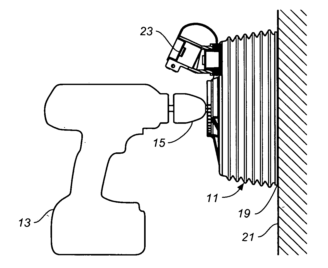
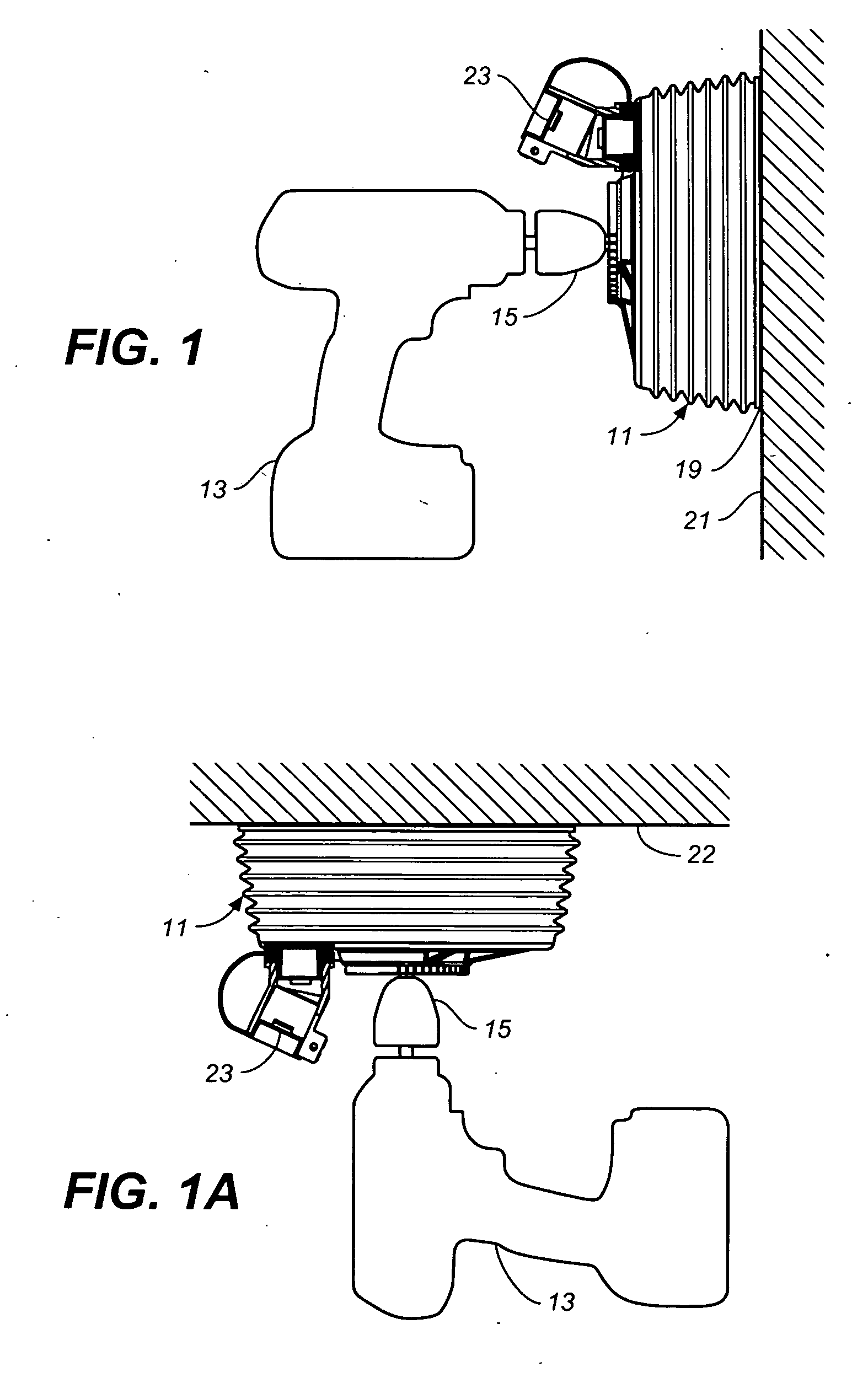
[0060] Referring now to the drawings, FIGS. 1 and 1A generally show how a debris shield in accordance with the invention, such as debris shield 11, is used with a hand drill 13 when cutting or drilling holes in a vertical or horizontal surface to shield the worker and surrounding work area from debris generated during the cutting operation. The other later-described embodiments of the invention would be used with a hand drill in a similar manner. The debris shield holds and covers a cutting or drilling implement (not shown and sometimes generically referred to herein as rotary surface working implements) having an arbor end that projects from the top of the drill shield and that is inserted into and held by the chuck 15 of hand drill 13. The illustrated debris shield includes a debris collection housing in the form of bellows housing 17, which has an open end and surface contact rim 19. When cutting or drilling a hole, the housing's surface contact rim is placed against a work surfa...


PUM

PropertyMeasurementUnit
rotationaaaaaaaaaa
anglesaaaaaaaaaa
vacuumaaaaaaaaaa

Abstract

A debris shield for a rotary tool or machine for collecting debris generated while cutting or drilling holes in a work surface has a debris collection housing having a top structure, side walls depending from said top cover structure to form a debris collection chamber, an open bottom with a surface contact rim, and a compression axis extending through the housing's top structure and bottom opening. In one aspect of the invention, the debris collection housing is a bellows housing with a vacuum port, and has a shank-holding and vent assembly in top structure of the bellows housing for receiving and rotatably holding the shank of a rotary surface working implement such as a drill bit, spade bit or hole saw. In another aspect of the invention the debris collection housing can be either a bellows type housing or rigid housing, and can have a vacuum port or not. In this aspect of the invention, the housing is provided with a chuck-arbor assembly having a chuck end and an arbor end rotatably mounted in the top structure of said debris collection housing so that it lies on a rotary axis that is substantially parallel to the compression axis of said debris collection housing. The chuck end of said chuck-arbor assembly is situated within said housing for receiving and holding the arbor end of a surface working implement, and the arbor end of said chuck-arbor assembly projects above the top structure of said housing such that the arbor end of said chuck-arbor assembly can be inserted into the chuck of a rotary tool such as a handle drill. In one embodiment, compression along the compression axis is provided by means of a bellows type housing; in another embodiment compression is provided by a chuck-arbor assembly having a spring loaded shaft which is slidably mounted in the top structure of the housing, such that the chuck end of the chuck-arbor assembly can be made to advance against the restoring force of the spring loaded shaft toward a work surface.

Description

CROSS-REFERENCE TO RELATED APPLICATIONS [0001] This application is a continuation-in-part of application Ser. No. 11 / 123,836 filed May 5, 2005, now pending, which claims the benefit of U.S. Provisional Application No. 60 / 569,171 filed May 7, 2004.BACKGROUND OF THE INVENTION [0002] The present invention generally relates to rotary tools or machine that generate debris when working on a surface, such as drilling, cutting or sanding, and more particularly relates to accessory attachments which collect debris generated by such tools or machines. [0003] Holes are typically cut in walls and other surfaces using a hand-operated drill with cutting or drilling attachments, such as hole saws, drill bits, and spade bits having a cutting or drill end and an arbor end with a polygonal cross-section which can be gripped by a drill chuck. Because drills and other hole-cutting tools produce dust and debris during the drilling or cutting operation, shields have been designed to fit onto the drill fo...

Claims


Application Information

Patent Timeline
Patent Type & Authority Applications(United States)
IPC IPC(8): B23B47/00
CPCB23B2270/30Y10T408/50Y10T408/5653B23Q11/0046
Inventor SKRADSKI, THOMAS J.CROSS, GARY L.
Owner SKRADSKI THOMAS J
Why Eureka
Try Eureka