Intraluminal Graft

a technology of intraluminal graft and graft, which is applied in the field of intraluminal graft, can solve the problems of lack of precise control and occlusion of the lumen, and achieve the effect of maximising the number of wires

Inactive Publication Date: 2007-03-22
WL GORE & ASSOC INC
View PDF99 Cites 7 Cited by
  • Summary
  • Abstract
  • Description
  • Claims
  • Application Information

AI Technical Summary

Benefits of technology

[0008] It is preferred that the one wire has a greater amplitude than at least the next adjacent one or two wires. This allows the wires at the end of the graft to be positioned more closely together than would be the case if they were all of the same amplitude. It is desirable to space the wires adjacent the and of the graft that will be placed “upstream” in the patient as close together as is possible as the neck of the aneurysm with which the graft is engaged can be quite short. Close spacing of the wires maximises the number of wires reinforcing that part of the graft in contact with the neck of the aneurysm. The spacing of the rest of the wires is desirably greater than those adjacent the one end of the graft as this avoids unnecessarily reducing the flexibility of the graft.
[0010] It is preferred that the edge of the one end of the graft is scooped out or scalloped between each projecting crest of the one wire. This reduces the possibility that a piece of the graft between those crests could project into the arterial lumen and partially occlude it or direct blood around the outside of the graft.
[0012] The wires are preferably formed of stainless steel or another metal or a plastic which is maleable and is biocompatible. Each wire is preferably woven into the fabric of the graft body to integrate the body and the reinforcing wires. This prevents any possibility of the wire reinforcement separating from the graft body during introduction of the graft or throughout its life. If the graft body is of a woven material the wires may be interwoven with the graft body during its production or alternatively they may be interwoven with the graft body after its manufacture. If the graft body is not woven but is knitted or of an impervious sheet material then the wires may be threaded through suitable holes formed in the graft body. The interweaving of the wires with the graft body has been found to be particularly desirable an it prevents separation of the wires from the graft body which could have serious adverse consequences. It has also been found that this technique is very good for causing the graft to expand effectively with the wires.
[0014] The intraluminal grafts according to this invention may be used to treat aneurysms or occlusive disease. In addition to treating aortic aneurysms they are particularly suitable for treating aneurysms of the femoral artery, the popliteal artery, the thoracic segment of the aorta, visceral arteries such as the renal and mesenteric arteries, the iliac artery and the sub-clavian artery. The presence of the metal wires in the intraluminal grafts according to this invention assists in placing the graft as the wires are X-ray detectable. As the wires are arrayed along the length of the graft the complete position of the graft in the body can be continuously monitored.
[0016] The ends of the wires are joined together to form a tail which is preferably on the outside of the graft body and is positioned to lie along its radially outer surface. The ends may be joined by welding, by being twisted together or in any other suitable manner. The ends of the wires may inadvertently perforate the vessel in which the graft is placed, however, any such perforation will be occluded by the graft body thus ensuring that such a perforation will not adversely affect the patient. The ends of adjacent wires are preferably spaced apart radially about the graft body so as not to affect its flexibility and to avoid a line of ends engaging the wall of the vessel. The ends of adjacent wires preferably project in opposite directions along the vessel body. When the intraluminal graft is inserted into a vessel those wire ends which engage the inside surface of the vessel wall will assist in preventing the graft from inadvertent movement along the vessel. Causing the end of alternate wires to project in opposite longitudinal directions along the graft body will assist in preventing longitudinal movement of the graft along the vessel in either direction.

Problems solved by technology

There are a number of problems associated with such known grafts.
These include the problem of twisting or kinking of the graft when it has to extend along a non-linear path which, twisting or kinking can lead to occlusion of the lumen of the grafts lack of precise control of the expansion of the graft in the lumen; avoidance of inadvertent separation of a supporting stent and the covering sleeve; and maintaining the graft against longitudinal movement along the lumen in which it is placed.

Method used


Image

  • Intraluminal Graft
  • Intraluminal Graft
  • Intraluminal Graft

Examples


Embodiment Construction

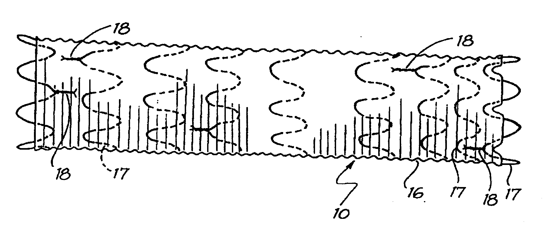
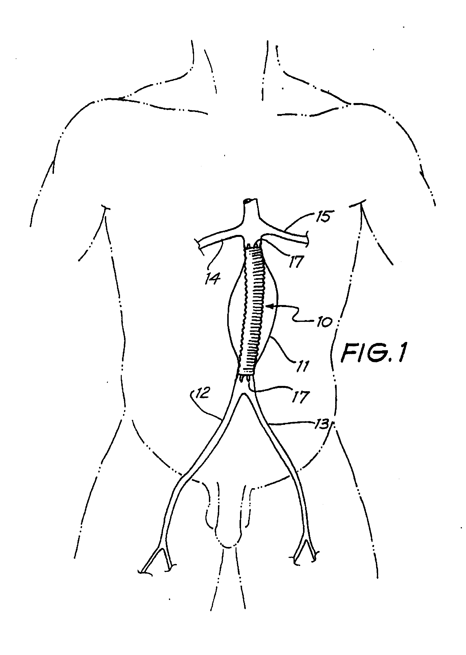
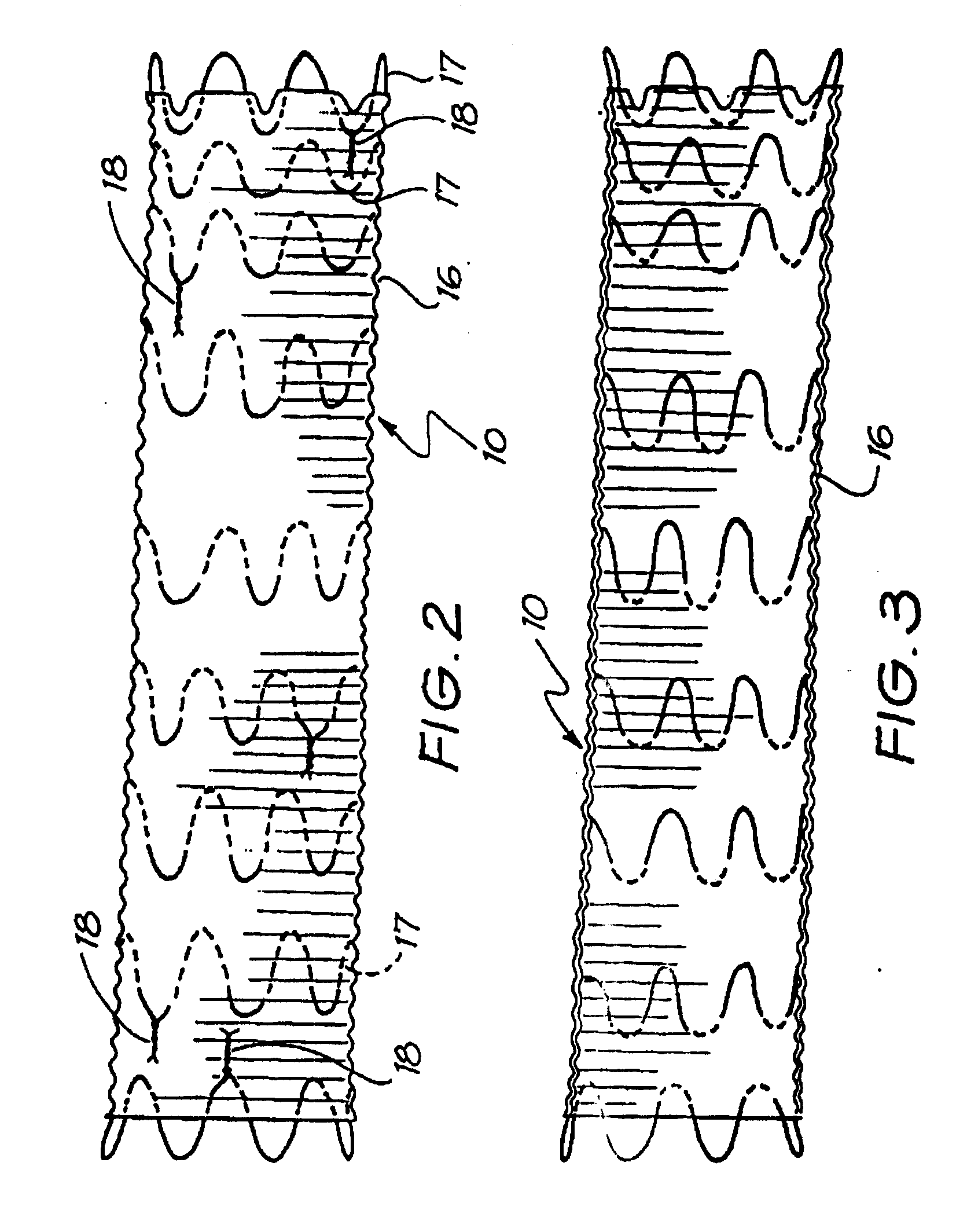
[0028] The intraluminal graft 10 is adapted for insertion transfemorally into a patient to achieve bridging and occlusion of the aneurysm present in the aorta. As is seen in FIG. 1 the aorta 11 is connected to the left and right femoral arteries 12 and 13. The aortic aneurysm is located between the renal arteries 14 and 15 and the junctions of the femoral arteries 12 and 13 with the aorta 11. The graft 10 is, as will be described subsequently in more detail, inserted inside a catheter introduced into one of the femoral arteries 12 or 13 in a leg of the patient. Once the catheter is located appropriately with its proximal end in the aorta 11 the graft 10 is ejected from the catheter and expanded so that each end is in intimate contact around its full periphery with the aorta 11. The graft 10 then bridges the aneurysm and isolates any thrombosis or gelatinuous material associated with the aneurysm outside the graft 10 to reduce the risk of embolisation.

[0029] The intraluminal graft 1...


PUM


Abstract

An intraluminal graft includes a tubular graft body extending along a cylindrical axis, a plurality of wires spaced apart from each other and arranged to circumferentially reinforce said tubular graft body along a substantial portion of its length, and a body surface including an inner surface region and an outer surface region. The body surface defines a plurality of apertures extending from an exterior space, and a first portion of a first wire is in the interior space while a second portion of the first wire is in the exterior space.

Description

FIELD OF INVENTION [0001] The present invention relates to an intraluminal graft for use in treatment of aneurysms or occlusive diseases. [0002] It is known to use stents and intraluminal grafts of various designs for the treatment of aneurysms such as aortal aneurysms and for the treatment of occlusive diseases such as the occlusion of blood vessels or like ducts such as the bile duct and the ureter (which are all hereinafter called “vessels”). It is known to form such an intraluminal graft of a sleeve in which is disposed a plurality of self expanding wire stents (see Balko A. et al., “Transfemoral Placement of Intraluminal Polyurethane Prosthesis for Abdominal Aortic Aneurysms”, Journal of Surgical Research 40, 305-309 (1986); Mirich D. et al, “Percutaneously Placed Endovascular Grafts for Aortic Aneurysms: Feasibility Study” Radiology, Vol. 170, No. 3, part 2, 1033-1037 (1989)). Such intraluminal grafts are inserted through the femoral artery into the aorta in a catheter. Upon t...

Claims


Application Information

Patent Timeline
Patent Type & Authority Applications(United States)
IPC IPC(8): A61F2/06A61F2/86
CPCA61F2/07A61F2/86A61F2/89A61F2002/075A61F2/958
Inventor WHITE, GEOFFREY H.YU, WELYUN
Owner WL GORE & ASSOC INC
Why Eureka
Try Eureka