Flexible flat cable, method and apparatus for assembling the same

a flat cable, flexible technology, applied in the direction of flat/ribbon cables, insulated conductors, cables, etc., can solve the problems of increasing material costs, and achieve the effect of reducing materials costs, preventing fingers from sliding, and without risk of bending

Inactive Publication Date: 2007-03-29
FUNAI ELECTRIC CO LTD
View PDF5 Cites 6 Cited by
  • Summary
  • Abstract
  • Description
  • Claims
  • Application Information

AI Technical Summary

Benefits of technology

[0024] In accordance with a preferred embodiment, such as illustrated above by way of example in the third aspect, it is possible to significantly reduce materials costs since the end portions of the conductive wire group may be reinforced by the hollow square reinforcing plate (formed by providing a through hole at the center of a reinforcing plate) and the central reinforcing plate extracted from the hollow square reinforcing plate, in which the combination of both the central reinforcing plate and hollow square reinforcing plate together corresponds to a comparable amount of material required for just one conventional reinforcing plate, it is possible to reduce material cost significantly.
[0025] In accordance with at least the fourth aspect, since the central reinforcing plate reinforces one end portion of the conductive wire group from the vicinity of the leading end through the base thereof, while the hollow square reinforcing plate also reinforces the other end portion of the conductive wire group from the leading end through the base thereof, thus the end portions of the conductive wire group can be inserted straight into connectors and function reliably as conductors, without risk of bending.
[0026] In accordance with at least the fifth aspect, since the zigzag-shaped outer peripheral edge of the central reinforcing plate and the zigzag-shaped inner peripheral edge of the hollow square reinforcing plate can be securely gripped between the fingers in order to insert the end portions of the conductive wire group into connectors, it is possible to prevent fingers from slipping when performing the insertion operation.
[0027] In accordance with at least the sixth aspect, since the concavo-convex anti-slip portions formed in the surfaces of the central reinforcing plate and the hollow square reinforcing plate can be securely grasped by the fingers when inserting the end portions of the conductive wire group into connectors, it is possible to prevent the fingers from slipping and to perform the insertion operation more reliably.
[0028] In accordance with at least the seventh aspect, since many recessed portions may be formed in the surfaces of the central reinforcing plate and the hollow square reinforcing plate at predetermined spacing, reducing the thickness thereof, it is possible to further reduce material cost. In addition, since grid reinforcing frames are left between the recessed portions, the end portions of the conductive wire group can thus be reinforced reliably with no reduction in strength and the grid reinforcing frames can additionally enhance the slip-resistance of the central reinforcing plate and the hollow square reinforcing plate.
[0029] In accordance with at least one example, as illustrated with regard to the eighth aspect, inter alia, the central reinforcing plate may be extracted from the reinforcing tape and fixed to one end portion of the conductive wire group in a first step, and then the reinforcing tape may be reused to extract the hollow square reinforcing plate to be fixed to the other end portion of the conductive wire group in a second step after the central reinforcing plate has been extracted from the reinforcing tape. Accordingly, many flexible flat cables can be assembled continuously and efficiently, and it is possible to significantly reduce materials costs because the central reinforcing plate and the hollow square reinforcing plate are both extracted from the same section of reinforcing tape.

Problems solved by technology

In the above-described conventional arrangement, two reinforcing plates 98 are fixed to the respective end portions 71 and 72 of the conductive wire group 7 so that the end portions 71 and 72 of the conductive wire group 7 are not bent when inserted into the connectors 5, and the reinforcing plates 98 each have a relatively large size and thickness, resulting in an increase in material cost.

Method used


Image

  • Flexible flat cable, method and apparatus for assembling the same
  • Flexible flat cable, method and apparatus for assembling the same
  • Flexible flat cable, method and apparatus for assembling the same

Examples


first embodiment

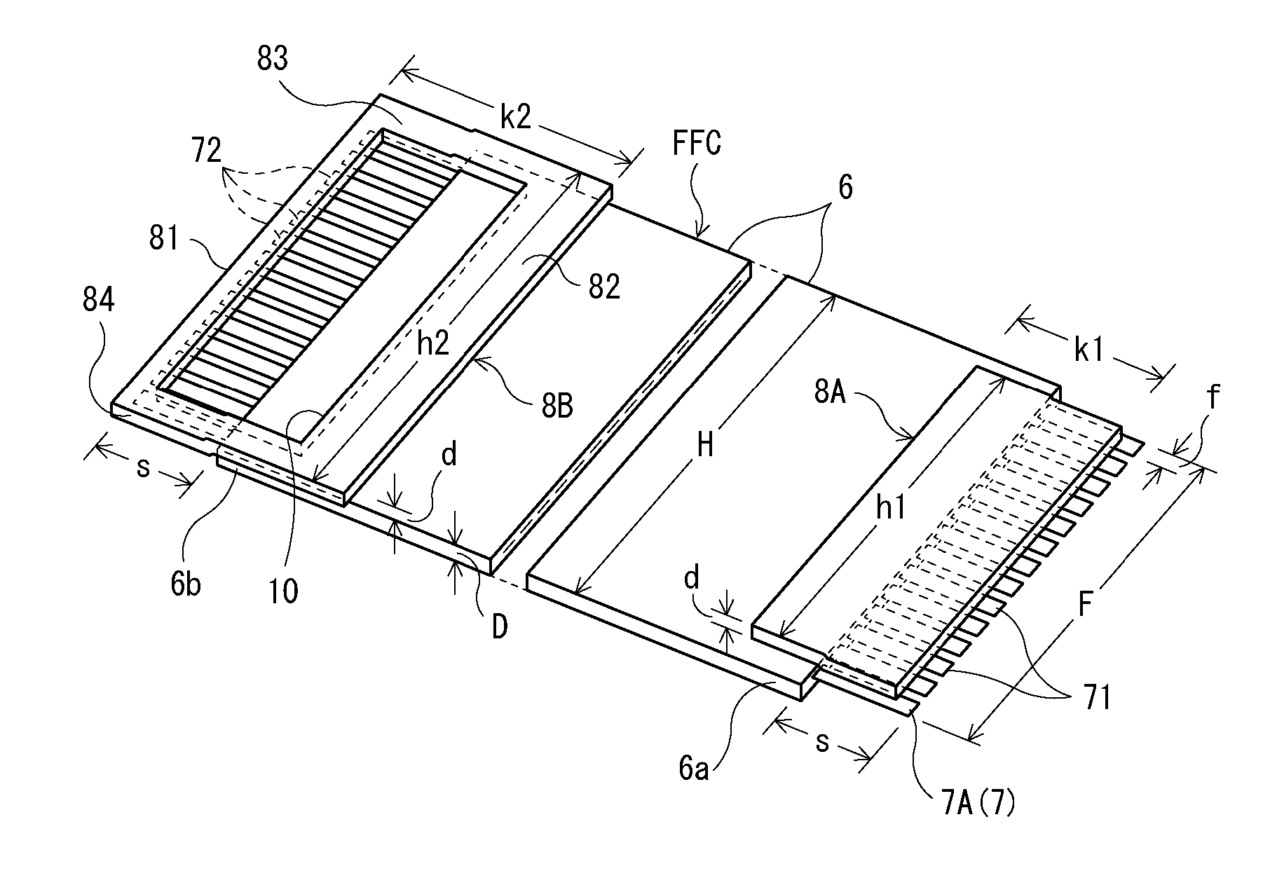
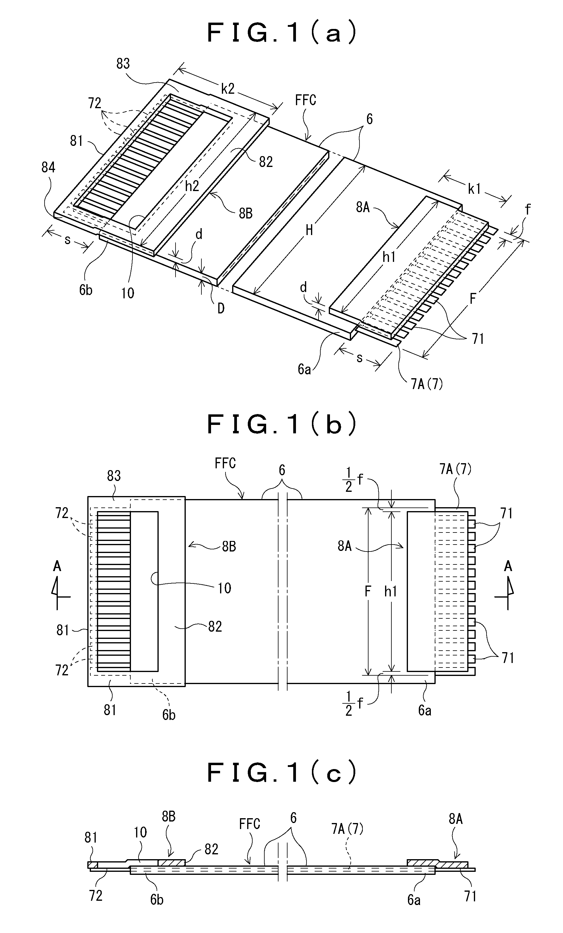
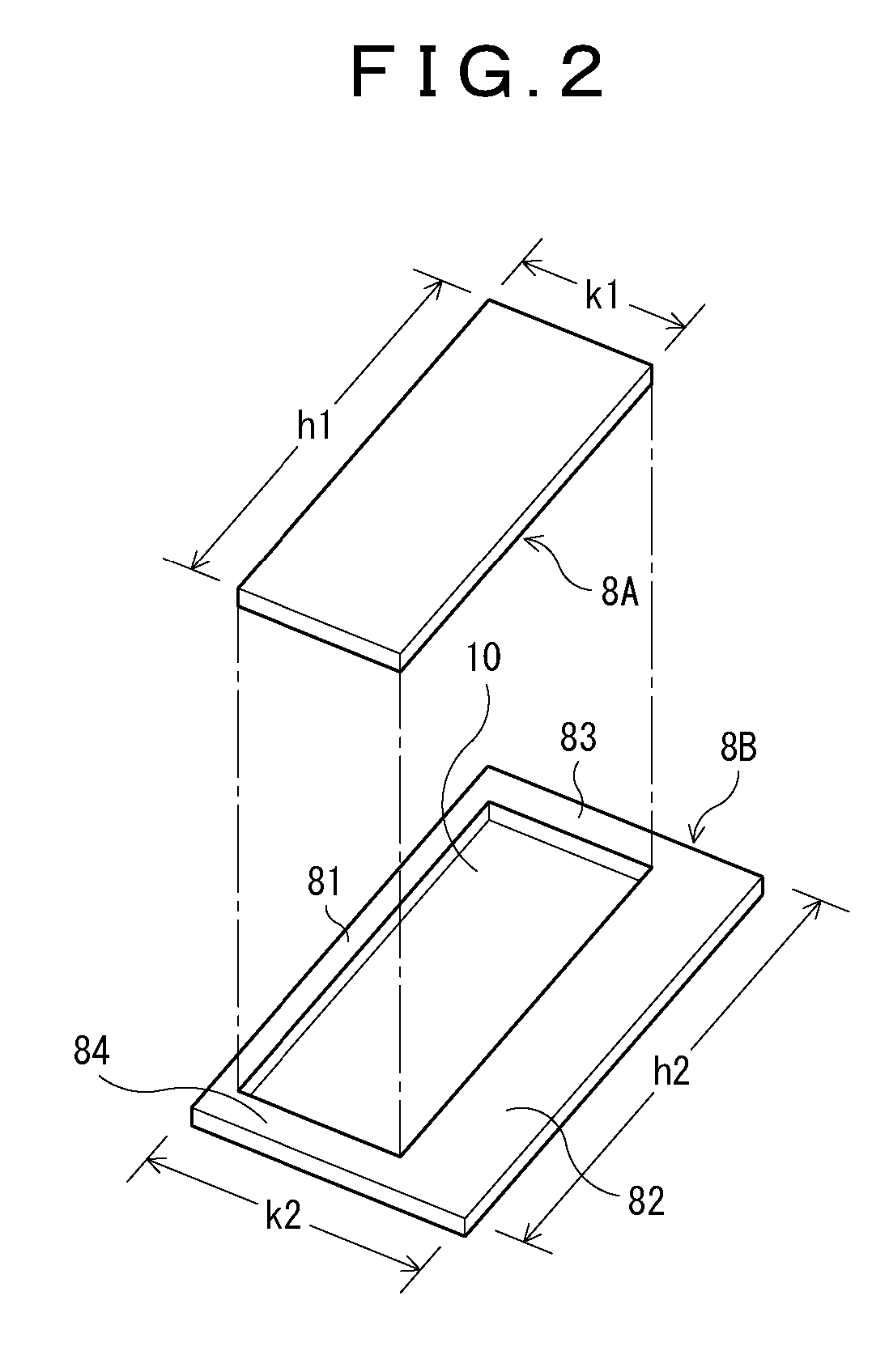
[0039] FIGS. 1(a), 1(b), 1(c) and 2 show a flexible flat cable FFC in which a hollow square reinforcing plate 8B formed by providing a through hole 10 at the center of a reinforcing plate and a central reinforcing plate 8A extracted from the reinforcing plate are used, the reinforcing plates 8A and 8B being fixed on an area extending from one surface at the respective end portions 6a and 6b of a cover 6 through one surface at the respective end portions 71 and 72 of a conductive wire group 7.

[0040] The central reinforcing plate 8A may be made of the same material as conventional reinforcing plates 98 (see FIGS. 9(a) through 9(c), for example), and the lateral width h1 of the central reinforcing plate may be set to a length obtained by subtracting the lateral width “f” of one conductive wire 7A from the lateral width F of the end portions 71 and 72 of the conductive wire group 7 (such that h1=F−f), while the longitudinal width k1 of the central reinforcing plate may be set to be gre...

fourth embodiment

[0052] Also, as shown in FIG. 7(b), with respect to an example of the fourth embodiment, many recessed portions 24 may be formed on the surfaces of the reinforcing plates 8A and 8B at predetermined spacing so that grid reinforcing frames 25 are left between the recessed portions 24. In accordance with this arrangement, since many recessed portions 24 are formed at predetermined spacing and correspondingly reduce the thickness “t” of the reinforcing plates 8A and 8B, it is possible to further reduce material cost. In addition, since the grid reinforcing frames 25 remain (preferably forming a lattice or grid-like pattern, as shown for example in FIG. 7(b)), the end portions 71 and 72 of the conductive wire group 7 can be reinforced reliably with no reduction in strength and the grid reinforcing frames 25 can further enhance the anti-slip effect. To give one possible example, the original thickness “d” of the reinforcing plates 8A and 8B may be 0.35 mm and the thickness “t” of the rece...


PUM

PropertyMeasurementUnit
thicknessaaaaaaaaaa
widthaaaaaaaaaa
thicknessaaaaaaaaaa

Abstract

A flexible flat cable and an apparatus for assembling the flexible flat cable are provided. The flexible flat cable has a conductive wire group including conductive wires disposed parallel to each other and arranged in a synthetic resin cover, in which both end portions and of the conductive wire group protrude outward from the end edges of the cover, and a pair of synthetic resin reinforcing plates are fixed to areas extending from one surface at the respective end portions of the cover through one surface at the respective end portions of the conductive wire group. One of the reinforcing plates includes a hollow square reinforcing plate formed by providing a through hole at the center of a reinforcing plate, and the other reinforcing plate includes a central reinforcing plate extracted from the hollow square reinforcing plate.

Description

BACKGROUND [0001] 1. Field of the Disclosure [0002] The present disclosure relates to a flexible flat cable such as used in, for example, a disk apparatus (e.g., a DVD player or DVD recorder) and a method and an apparatus for assembling the flexible flat cable. [0003] FIGS. 8(a) through 8(c) show one non-limiting example of a disk apparatus, in which a main circuit board 3 is arranged on one side of a disk player main body 2 in a chassis 1 and an AV circuit board 4 is arranged below the main circuit board 3, the circuit boards 3 and 4 being connected via connectors 5 and a flexible flat cable FFC, in which the tray 2a of the disk player main body 2 is moved in the forward direction “a” based on an unloading signal and a disk D is placed on the tray 2a, and then the tray 2a is moved in the backward direction “b” based on a loading signal to perform recording, reproduction, or erasing for the disk D. [0004] 2. Related Art [0005] There has conventionally been proposed a flexible flat c...

Claims


Application Information

Patent Timeline
Patent Type & Authority Applications(United States)
IPC IPC(8): H01B7/08
CPCH01R12/592H01R43/28H01R43/007
Inventor SUEKUNI, MASATO
Owner FUNAI ELECTRIC CO LTD
Why Eureka
Try Eureka