Engine suspension pylon for aircraft

a technology for aircraft and suspension pylons, which is applied in the direction of machine supports, other domestic articles, transportation and packaging, etc., can solve the problems of relatively large losses and loss in aircraft performance, and achieve the effects of reducing aerodynamic disturbance, reducing dimension, and advantageously reducing generated drag

Active Publication Date: 2007-03-29
AIRBUS OPERATIONS (SAS)
View PDF2 Cites 31 Cited by
  • Summary
  • Abstract
  • Description
  • Claims
  • Application Information

AI Technical Summary

Benefits of technology

[0016] Consequently, such a configuration clearly reduces the dimension below the lower spar of the box, and therefore reduces aerodynamic disturbances adjacent to the engine forward attachment. Therefore for an attachment body with the same dimensions, the generated drag is advantageously lower than the drag that occurs in prior art.
[0017]

Problems solved by technology

This arrangement has a non-negligible disadvantage which is that the entire attachment body projects downward from the box, which results in a large vertical dimension of the pylon above the engine and therefore major aerodynamic disturbances adjacent to the engine forward attachment, t

Method used


Image

  • Engine suspension pylon for aircraft
  • Engine suspension pylon for aircraft
  • Engine suspension pylon for aircraft

Examples


Embodiment Construction

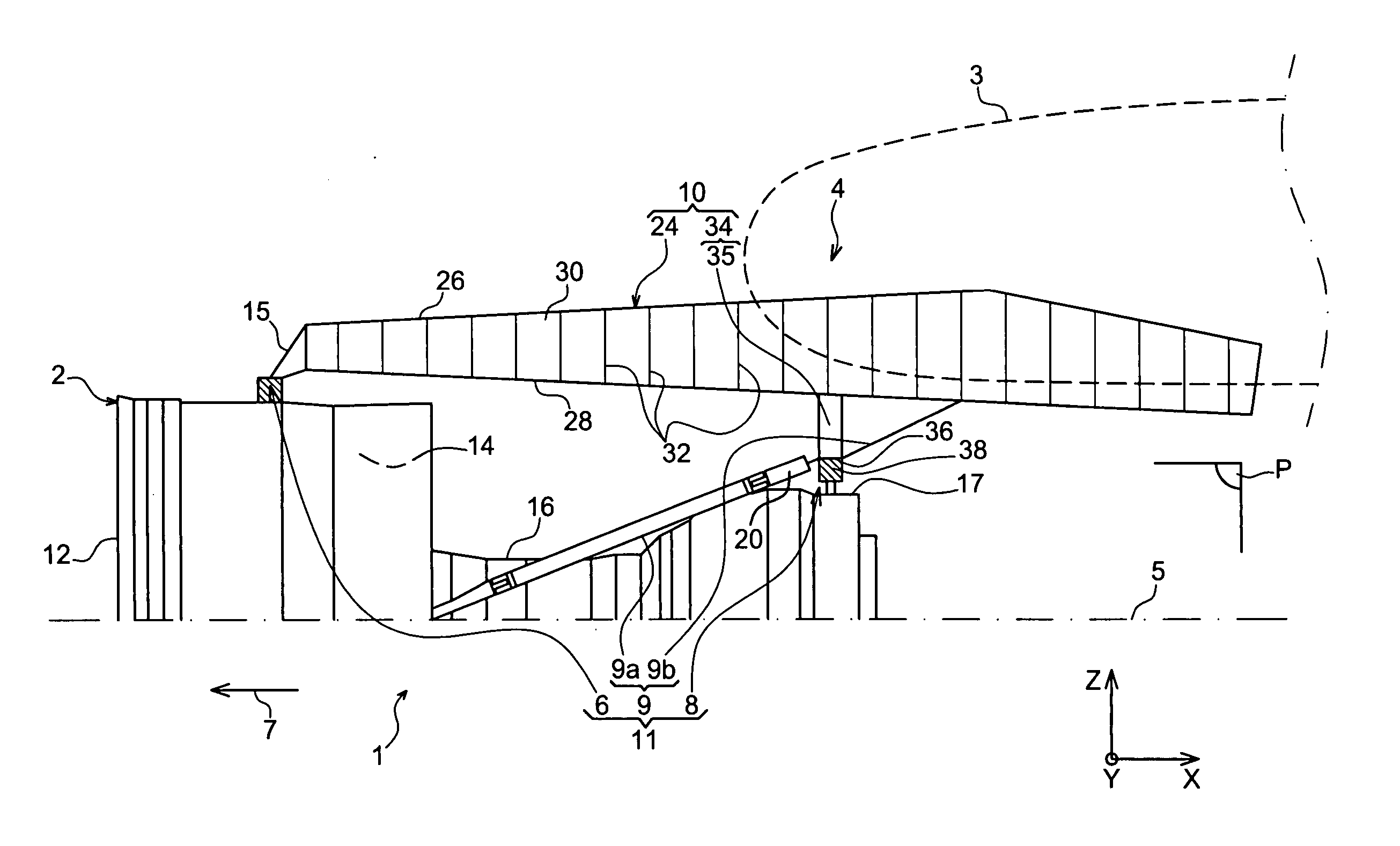
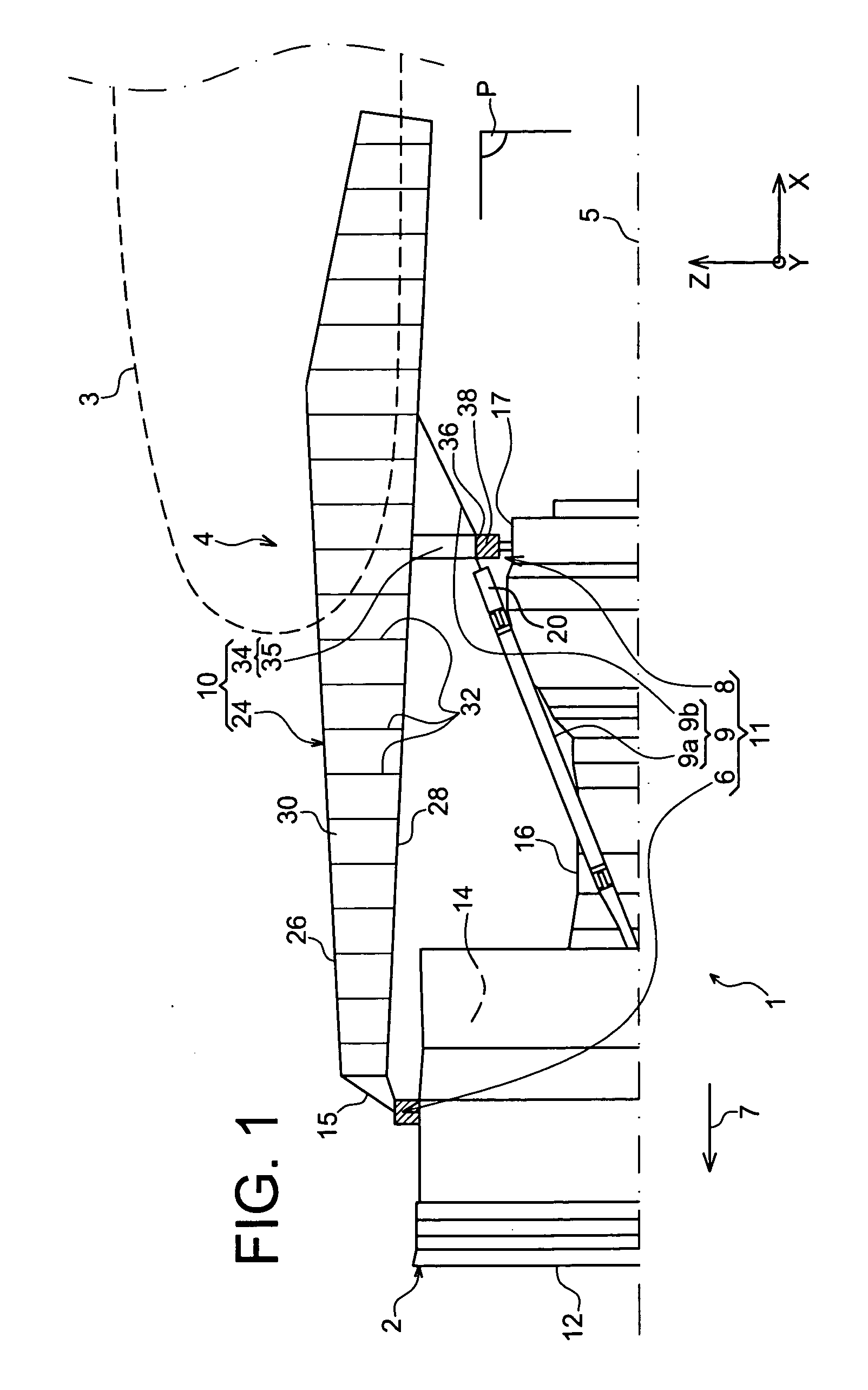
[0027] With reference to FIG. 1, the figure shows an engine assembly 1 for an aircraft designed to be fixed under a wing 3 of this aircraft, this assembly 1 according to this invention being provided with a suspension pylon 4 in the form of a preferred embodiment of this invention.

[0028] Globally, the engine assembly 1 includes an engine such as a turbojet 2 and the suspension pylon 4, the suspension pylon having in particular a rigid structure 10 and an engine mounting system 11 composed of a plurality of engine attachments 6, 8 and a device 9 for resistance of thrusts generated by the turbojet 2, the mounting system 11 therefore being inserted between the engine and the rigid structure 10 mentioned above. For information, note that the assembly 1 is designed to be surrounded by a pod (not shown in this figure), and that the suspension pylon 4 includes another series of attachments (not shown) for suspension of this assembly 1 under the aircraft wing.

[0029] Throughout the followi...


PUM


Abstract

The invention refers to a suspension pylon (4) for an aircraft engine (2), the pylon including a rigid structure (10) forming a box provided with a lower spar (28) and an upper spar (26), and an engine mounting system (11) installed fixed on the structure (10) and in particular including a forward attachment (6) with an attachment body provided with a horizontal fixing surface (40) held in contact with a horizontal fixing surface (38) of the structure (10). According to the invention, the attachment body is arranged such that its horizontal fixing surface (40) is located along a vertical direction (Z) of the pylon, upwards from a forward end (28a) of the lower spar and downwards from a forward end (26a) of the upper spar. Furthermore, the structure (10) includes at least one forward fitting (42a, 42b) making up a forward closing rib (36) of the box, this fitting (42a, 42b) defining said horizontal fixing surface (38).

Description

TECHNICAL DOMAIN [0001] This invention relates in general to an engine assembly for an aircraft of the type including an engine, a suspension pylon, and an engine mounting system provided with a plurality of engine fasteners and being inserted between a rigid structure of the suspension pylon and the engine.[0002] The invention also relates to such a suspension pylon for the aircraft engine. [0003] The invention may be used on any aircraft type, for example fitted with turbojets or turboprops. [0004] This type of suspension pylon is also called an EMS (Engine Mounting Structure), for example that can be used to suspend a turboengine below the aircraft wing, or to fit this turboengine above this same wing. STATE OF PRIOR ART [0005] Such a suspension pylon is designed to form a connecting interface between an engine such as a turbojet and a wing of the aircraft. It transmits forces generated by its associated turbojet to the structure of this aircraft, and is also used for routing fue...

Claims


Application Information

Patent Timeline
IPC IPC(8): B64D27/00
CPCB64D2027/266B64D27/26
Inventor LAFONT, LAURENTJOURNADE, FREDERICLABARTHE, CHRISTOPHE
Owner AIRBUS OPERATIONS (SAS)
Why Eureka
Try Eureka