
Liquid crystal display apparatus and monitor system having the same

Inactive Publication Date: 2007-03-29
DENSO CORP
View PDF14 Cites 25 Cited by
  • Summary
  • Abstract
  • Description
  • Claims
  • Application Information

AI Technical Summary

Benefits of technology

[0012] In view of the above-described problem, it is an object of the present invention to provide a liquid crystal display apparatus having a reduced blurring and flicker over a wide temperature range, and a monitor system having the same.
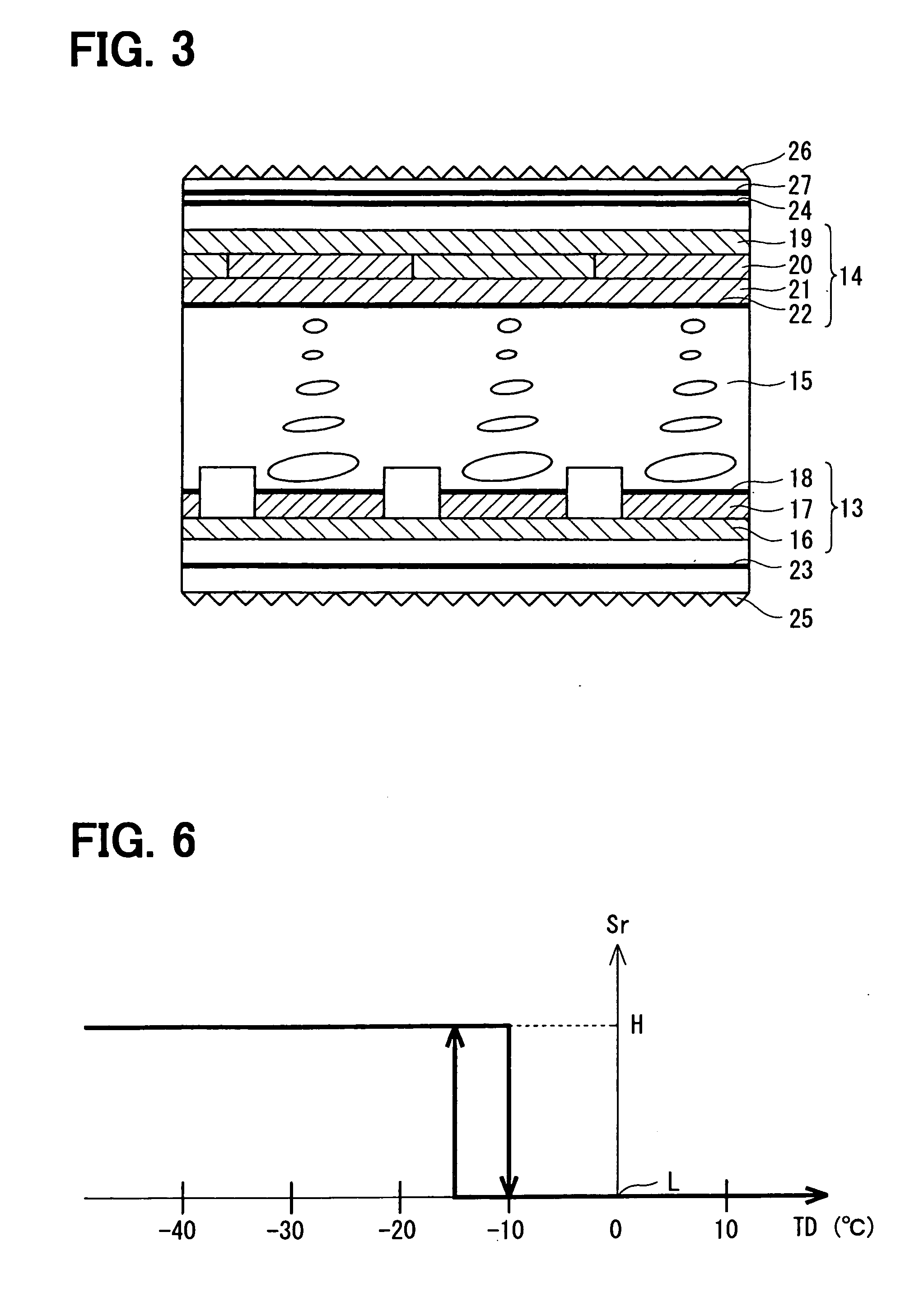
[0014] In the liquid crystal display apparatus, the time interval is gradually controlled by the field period. When the temperature of the liquid crystal layer is low and viscosity of the liquid crystal layer is high, the control circuit reverses the polarity of the voltage at a longer interval. Thus, while the liquid crystal display apparatus is alternately driven with the voltage of opposite polarity, the responsiveness of the liquid crystal layer can be improved without a reduction in the amount contained in a moving image. Consequently, the liquid crystal display apparatus can display the moving image with a reduced blurring at a low temperature. In contrast, when the temperature of the liquid crystal layer is high and the viscosity of the liquid crystal layer is low, the control circuit reverses the polarity of the voltage at a shorter interval. Thus, the liquid crystal display apparatus can display the moving image with the reduced flicker at a high temperature.

Problems solved by technology

However, problems still need to be solved before the LCD replaces a cathode-ray tube (CRT).
In the LCD apparatus disclosed in JP-2004-219933A, JP-2004-177575A, and US 2005 / 0062712A1, although the field frequency changes in accordance with the temperature of the liquid crystal panel in the direct or pseudo manner, the LCD apparatus may not smoothly display the images.

Method used


Image

  • Liquid crystal display apparatus and monitor system having the same
  • Liquid crystal display apparatus and monitor system having the same
  • Liquid crystal display apparatus and monitor system having the same

Examples


Embodiment Construction

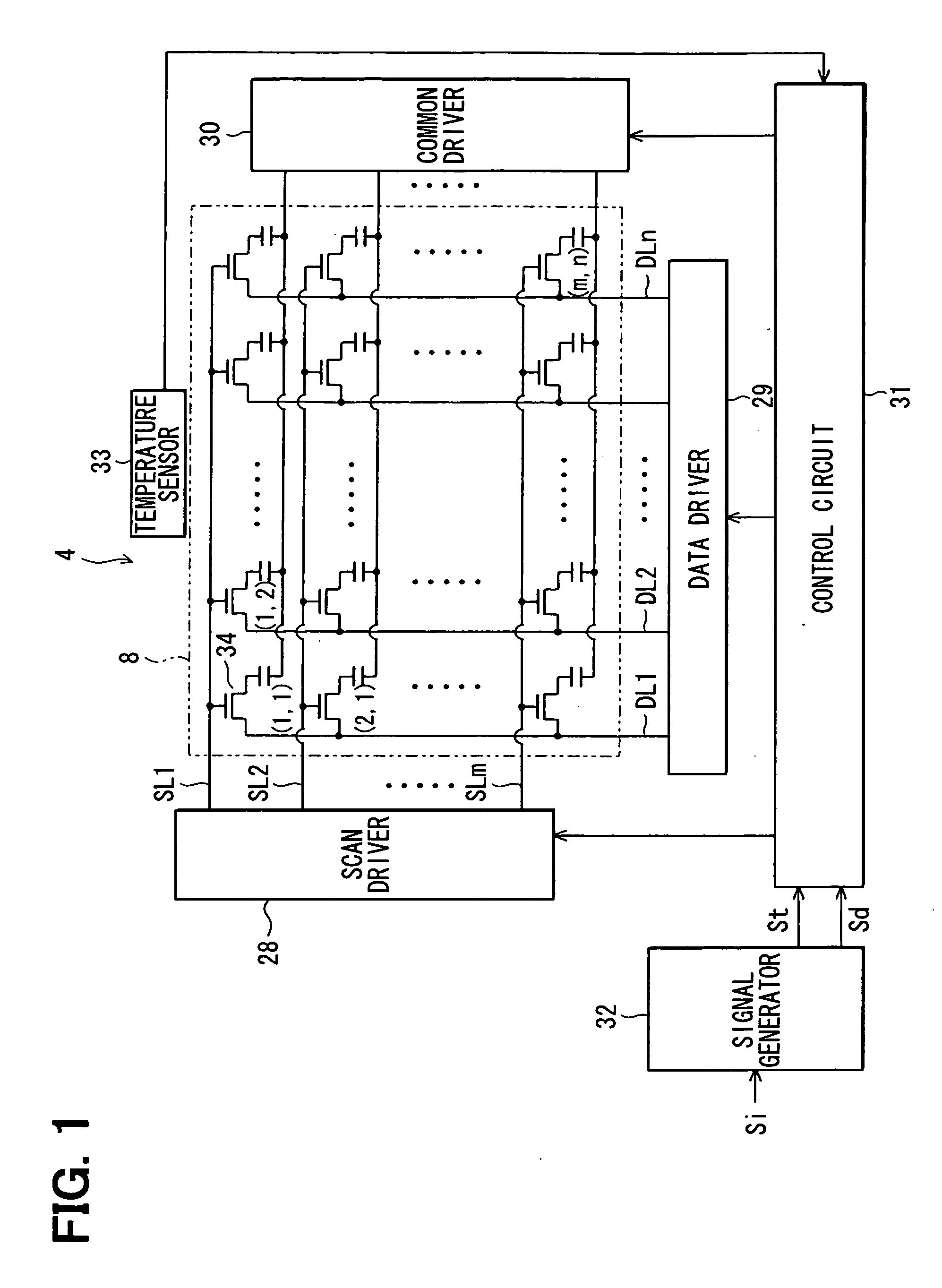
[0022] Referring to FIG. 4, a rear view monitor system 6 is installed in a vehicle 1. The monitor system 6 includes a camera unit 3 mounted on the rear of the vehicle 1, a liquid crystal display (LCD) apparatus 4 mounted on an instrument panel of the vehicle 1, and a display controller 5. The camera unit 3 has a charge-coupled device (CCD) camera 2 that provides images behind the vehicle 1 in color. The display controller 5 receives image signals from the camera 2, processes the received image signals, and outputs the processed image signals to the LCD apparatus 4. Thus, the LCD apparatus 4 displays the images behind the vehicle 1. When a car-navigation system is also installed in the vehicle 1, the car-navigation system and the monitor system 6 may share the LCD apparatus 4.

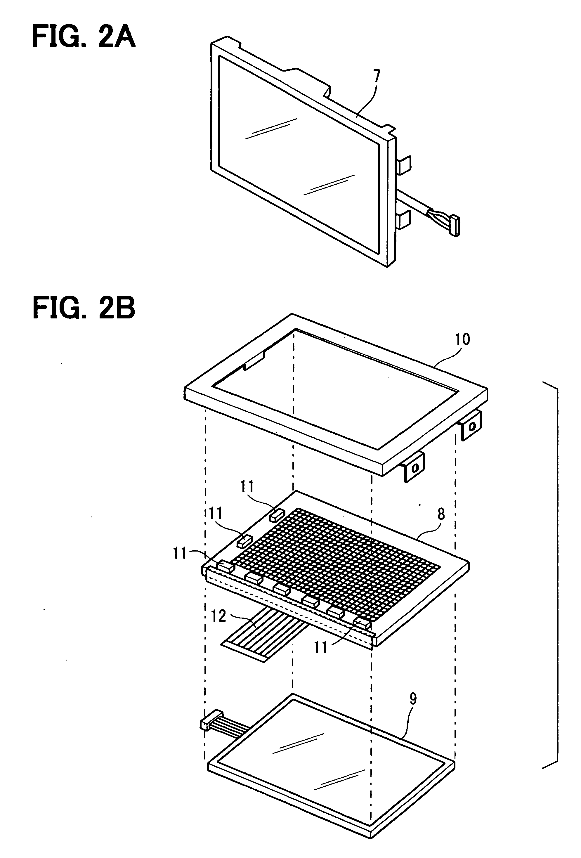
[0023] Referring to FIGS. 2A and 2B, a panel portion 7 of the LCD apparatus 4 includes a LCD panel 8, a backlight panel 9, and a front case frame 10. The backlight panel 9 is placed on the back side of the LCD ...


PUM


Abstract

A liquid crystal display apparatus includes a liquid crystal panel having a matrix of pixels, a control circuit, and a temperature sensor. The temperature sensor directly or indirectly detects a temperature of the liquid crystal panel. The control circuit reverses a polarity of a voltage applied to each pixel at a time interval variable with the detected temperature, while keeping a field frequency constant. The time interval is a positive integer multiple of the reciprocal of a field frequency, i.e., a positive integer multiple of a field period. When the temperature of the liquid crystal layer is low, the control circuit reverses the polarity of the voltage at a longer time interval. In contrast, when the temperature of the liquid crystal layer is high, the control circuit reverses the polarity of the voltage at a shorter time interval.

Description

CROSS REFERENCE TO RELATED APPLICATION [0001] This application is based on and incorporates herein by reference Japanese Patent Application No. 2005-275651 filed on Sep. 22, 2005. FIELD OF THE INVENTION [0002] The present invention relates to an active matrix liquid crystal display apparatus and a monitor system having the same. BACKGROUND OF THE INVENTION [0003] Recently, a liquid crystal display (LCD) has been developed that has high resolution, wide viewing angle, and low power consumption. However, problems still need to be solved before the LCD replaces a cathode-ray tube (CRT). For example, in a twisted nematic (TN) LCD, moving images may appear blurred, i.e., leave a ghost or trail across the LCD at low temperature. [0004] An electro optical panel disclosed in JP-2004-219933A includes a temperature compensation device having a temperature detection section to detect temperature of an image display area. Duration of application of a drive signal is increased in accordance with...

Claims


Application Information

Patent Timeline
IPC IPC(8): G09G3/36G09G3/18
CPCG09G3/3614G09G3/3648G09G2320/041G09G2320/0261G09G2320/0247
Inventor NAKAMURA, YUKOSUZUKI, ISAMU
Owner DENSO CORP
Learn More