Color processing method and apparatus thereof, and installer of device driver

a color processing and driver technology, applied in the field of color processing, can solve the problems of inability to achieve high-speed color matching processing, large amount of time, and complicated arithmetic processing for the creation of the conversion function, and achieve the effect of reducing the load required for modifying the integrated conversion characteristic data

Inactive Publication Date: 2007-03-29
CANON KK
View PDF5 Cites 12 Cited by
  • Summary
  • Abstract
  • Description
  • Claims
  • Application Information

AI Technical Summary

Benefits of technology

[0011] According to the present invention, integrated color conversion data can be efficiently and appropriately generated.
[0013] According to the present invention, integrated color conversion data which becomes unnecessary can be efficiently deleted.
[0017] According to the present invention, since integrated conversion characteristic data to be modified is determined based on the use log of the integrated conversion characteristic data, the load required to modify the integrated conversion characteristic data can be reduced.

Problems solved by technology

Creation of the conversion function requires complicated arithmetic processing and much time.
Therefore, when the conversion function is created according to the viewing conditions for every color matching, high-speed color matching processing cannot be attained.
In such color matching system, if respective color conversions are applied to input color data by calculations, enormous amounts of time are required.
However, when the plurality of color conversions are integrated every time color matching is applied to the input color data, integration of the color conversions requires much time, and may cause a throughput drop of the color matching processing.

Method used


Image

  • Color processing method and apparatus thereof, and installer of device driver
  • Color processing method and apparatus thereof, and installer of device driver
  • Color processing method and apparatus thereof, and installer of device driver

Examples


first embodiment

[Color Conversion Data Creation Sequence]

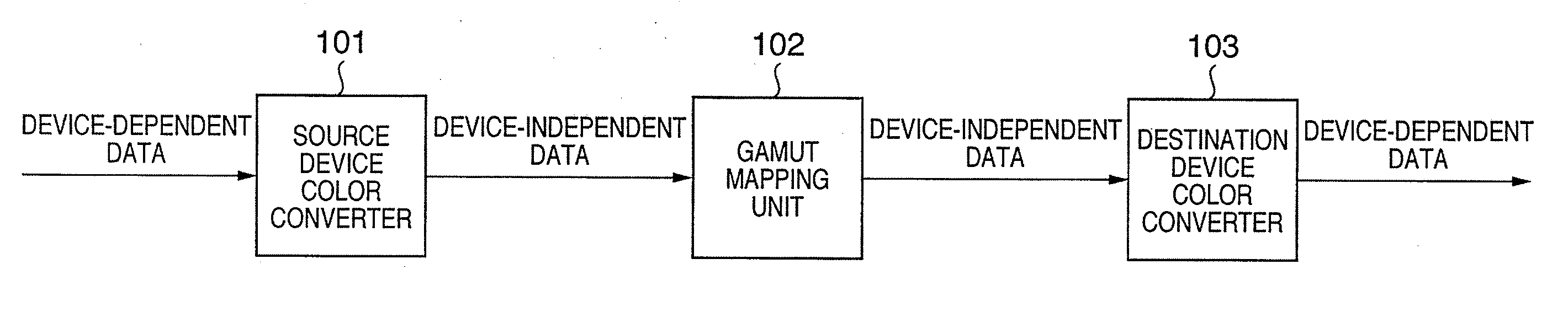
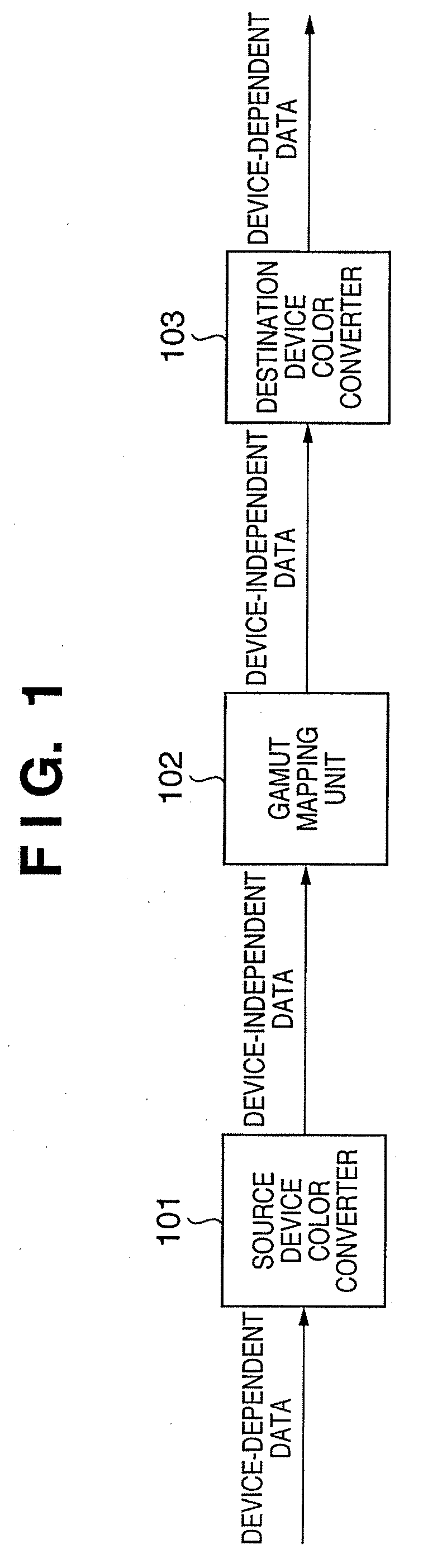
[0045] A sequence for creating color conversion data in the system shown in FIG. 1 will be described first.

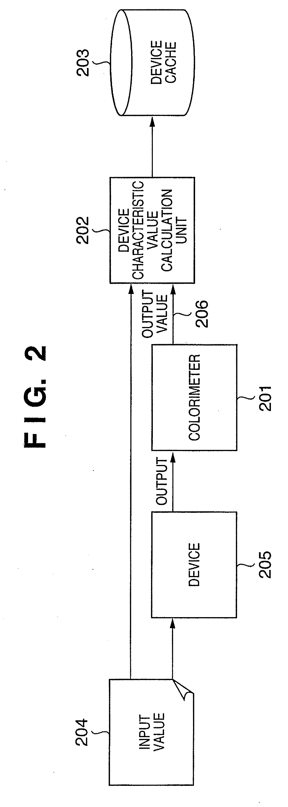
[0046]FIG. 2 is a diagram for explaining the sequence for creating color conversion data required when the source device is a monitor and the destination device is a CMYK printer.

[0047] An input value 204 such as RGB, CMYK, or the like, which corresponds to an Lab value of each grid point of grids obtained by evenly dividing, e.g., an Lab color space is input to a device 205 (monitor and CMYK printer). A color output from the device 205 is measured by a colorimeter 201 to obtain an output value (Lab value) of the device corresponding to the input Lab value. In this manner, data indicating correspondence between the input Lab value and output Lab value, i.e., the color reproduction characteristics of the device 205, is obtained. A device characteristic value calculation unit 202 calculates color conversion data for each device, e.g., a...

second embodiment

[0080] Installation processing according to the second embodiment will be described hereinafter. Note that the same reference numerals in the second embodiment denote the same parts as in the first embodiment, and a detailed description thereof will be omitted.

[0081] A raster image processor (RIP) system will be described below as an example of a color management system (CMS). However, any other CMSs may be used as long as the system can determine a color conversion system before color conversion.

[0082]FIG. 12 is a diagram showing the arrangement of the RIP system which performs color management.

[0083] Clients 1201 to 1203 send image data which are described in a page description language (PDL) and the like to an RIP server 1204 to instruct to output images. The RIP server 1204 is connected to a printer 1205. Upon reception of image data from one of the clients 1201 to 1203, the RIP server 1204 executes processing such as RIP, color conversion, and the like, and outputs a print j...

third embodiment

[0097] Color processing according to the third embodiment will be described hereinafter.

[0098]FIG. 16 is a block diagram showing the arrangement of an image processing apparatus of the third embodiment.

[0099] A CPU 2101 executes programs stored in a ROM 2102 and hard disk drive (HDD) 2108 using a RAM 2103 as a work memory. The CPU 2101 controls respective components to be described below via a system bus 2104, thus executing various kinds of processing including color processing to be described later.

[0100] An input interface 2105 comprises a serial bus interface such as USB, IEEE1394, or the like, which connects an input device 2106 that includes a keyboard, mouse, digital camera, scanner, and the like. The CPU 2101 can load data from the input device 2106 via the input interface 2105. Note that the CPU 2101 can also load device information unique to the input device 2106 such as a model name, gamut information, and the like of a digital camera.

[0101] An HDD interface 2107 comp...


PUM


Abstract

Creation of integrated color conversion data for color processing requires a large computation volume and much time in case of a device and GMA used for the first time. Hence, first color conversion data is stored in a memory, second color conversion data different from the first color conversion data is retrieved, and integrated color conversion data is generated from the first color conversion data and the second color conversion data. The generated integrated color conversion data is stored in the memory, so that the integrated color conversion data is read out from the memory and is used upon application of color processing according to the first color conversion data and the second color conversion data to color data.

Description

BACKGROUND OF THE INVENTION [0001] 1. Field of the Invention [0002] The present invention relates to color processing for converting image data of an input device into that for an output device, and installation, uninstallation, and creation of conversion characteristic data for the color processing. [0003] 2. Description of the Related Art [0004] Japanese Patent Application Laid-Open No. 2000-50086 describes a method of implementing high-precision color matching between an input image and output image independently of the viewing conditions on the input side and output side. This technique initially converts input data which depends on the color space of an input device into data of a color space that does not depend on any devices based on the viewing conditions on the input side via a conversion table, conversion matrix, or conversion function (to be collectively referred to as a “conversion function” hereinafter). Note that the color space of the input device will be referred to...

Claims


Application Information

Patent Timeline
Patent Type & Authority Applications(United States)
IPC IPC(8): H04N1/60
CPCH04N1/6058H04N1/603
Inventor MATSUI, TOMOHIRONASHIZAWA, HIROAKI
Owner CANON KK
Why Eureka
Try Eureka