Image processing apparatus and method for image resizing matching data supply speed

a technology of image processing and data supply speed, which is applied in the direction of geometric image transformation, processing architecture/configuration, instruments, etc., can solve the problems of inefficient processing, difficult sequential processing at constant intervals with respect to any given magnification factor, and difficult sequential processing at arbitrary magnification sequentially, etc., to achieve the effect of being ready to process

Active Publication Date: 2007-03-29
CYPRESS SEMICON CORP
View PDF8 Cites 12 Cited by
  • Summary
  • Abstract
  • Description
  • Claims
  • Application Information

AI Technical Summary

Benefits of technology

[0021] According to at least one embodiment of the present invention, an image reduction is performed after an enlargement at an integer magnification factor is performed, thereby producing an image having desired magnification. With this provision, line data scanned in the main scan direction of an image can be

Problems solved by technology

This is because it is difficult to perform enlargement at arbitrary magnification in a sequential manner by matching the speed of the output of the image sensor.
This makes it difficult to perform sequential processing at consta

Method used


Image

  • Image processing apparatus and method for image resizing matching data supply speed
  • Image processing apparatus and method for image resizing matching data supply speed
  • Image processing apparatus and method for image resizing matching data supply speed

Examples


Embodiment Construction

[0045] In the following, embodiments of the present invention will be described with reference to the accompanying drawings.

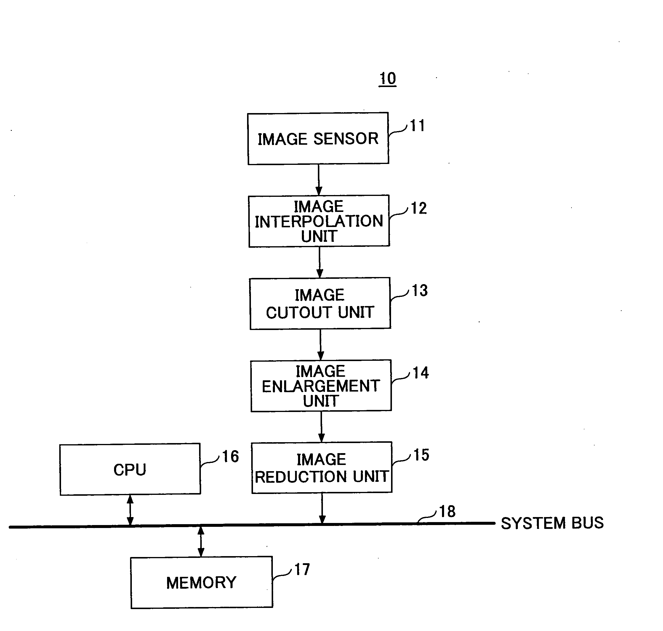
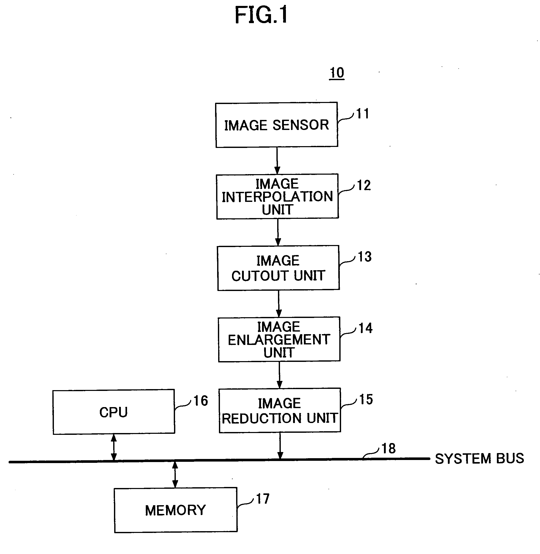
[0046]FIG. 1 is a block diagram showing an example of the configuration of an image processing apparatus according to the present invention. An image processing apparatus 10 shown in FIG. 1 includes an image sensor 11, an image interpolation unit 12, an image cutout unit 13, an image enlargement unit 14, an image reduction unit 15, a CPU 16, a memory 17, and a system bus 18.

[0047] The image sensor 11 may be a solid-state imaging device such as a CCD or CMOS, and has a light detecting section in which a plurality of photodiodes are arranged in matrix. These photodiodes constitute individual pixels for the imaging purpose. Incident light is subjected to photoelectric conversion on a pixel-by-pixel basis. Electric charge obtained by the photoelectric conversion is stored in an electric charge storage section for readout. The readout image signal is then amplifie...


PUM


Abstract

An image processing apparatus includes a data supply node to receive line data scanned in a main scan direction of an image, an image enlargement unit coupled to the data supply node to apply to the line data an enlargement process for enlarging the image by an enlargement factor equal to an integer so as to produce enlarged data at an output node, and an image reduction unit coupled to the output node of the image enlargement unit to apply to the enlarged data a reduction process for reducing the enlarged image by a desired reduction factor so as to produce reduced data at an output node.

Description

CROSS-REFERENCE TO RELATED APPLICATIONS [0001] The present application is based upon and claims the benefit of priority from the prior Japanese Patent Applications No. 2005-268216 filed on Sep. 15, 2005 and No. 2006-181692 filed on Jun. 30, 2006, with the Japanese Patent Office, the entire contents of which are incorporated herein by reference. BACKGROUND OF THE INVENTION [0002] 1. Field of the Invention [0003] The present invention generally relates to image processing apparatuses and image processing methods, and particularly relates to an image processing apparatus and image processing method for enlarging and reducing an image. [0004] 2. Description of the Related Art [0005] Enlargement and reduction of a digital image is a process of resampling that changes the sampling intervals corresponding to pixel positions of an original image into different sampling intervals. In general, such process requires that the pixel values of the original image be interpolated by newly generated...

Claims


Application Information

Patent Timeline
IPC IPC(8): G06K9/32
CPCH04N1/3875G06T3/4007G06T1/20G06T3/00G06T3/40
Inventor KUROKI, KENICHIROKUDO, TOSHIO
Owner CYPRESS SEMICON CORP
Why Eureka
Try Eureka