Hybrid screw for composite lumber and wood

a hybrid screw and composite lumber technology, applied in the direction of screws, threaded fasteners, fastening means, etc., can solve the problems of undesirable irregularities in the mounting and string, and achieve the effect of increasing the clamping

Inactive Publication Date: 2007-03-29
ROMANO MARK +1
View PDF8 Cites 7 Cited by
  • Summary
  • Abstract
  • Description
  • Claims
  • Application Information

AI Technical Summary

Benefits of technology

[0005] In accordance with the present invention, the disadvantages of prior screws used in composite lumber members, as discussed above, have been overcome. The screw of the present invention has at least one disruptive surface that cuts composite material away from the composite lumber member as the screw is driven into the member to prevent a mound and / or strings from being formed that are attached to the composite lumber member when the screw is set therein. Moreover, the screw of the present invention may be used with conventional wood members wherein the screw of the present invention provides increased clamping when driven into a wood member to fasten the wood member to a support member or the like.
[0006] More particularly, the screw of the present invention includes a head portion at an end of the screw opposite a pointed end of the screw. The screw has a threaded portion that extends to or adjacent the pointed end of the screw. The screw also has a cutter portion disposed between the head and threaded portions of the screw, the cutter portion having a disruptive surface that cuts composite material away from the composite member as the screw is driven into the composite member to prevent irregularities in the otherwise flat surface of the composite lumber member when the screw is set. More particularly, the screw of the present invention prevents a mound of composite material from being formed about the head of the screw when the screw is set into the composite lumber member where the mound is still attached to the composite lumber member. Similarly, the screw of the present invention prevents strings of the composite material from being formed where the strings are still attached to the composite lumber member when the screw is set.

Problems solved by technology

Known screws that are currently used to attach a composite lumber member to another member have been found to cause irregularities in the composite lumber member when those screws are driven into the member.
These mounds and strings form undesirable irregularities in the otherwise flat surface of the composite lumber member.

Method used


Image

  • Hybrid screw for composite lumber and wood
  • Hybrid screw for composite lumber and wood

Examples


Embodiment Construction

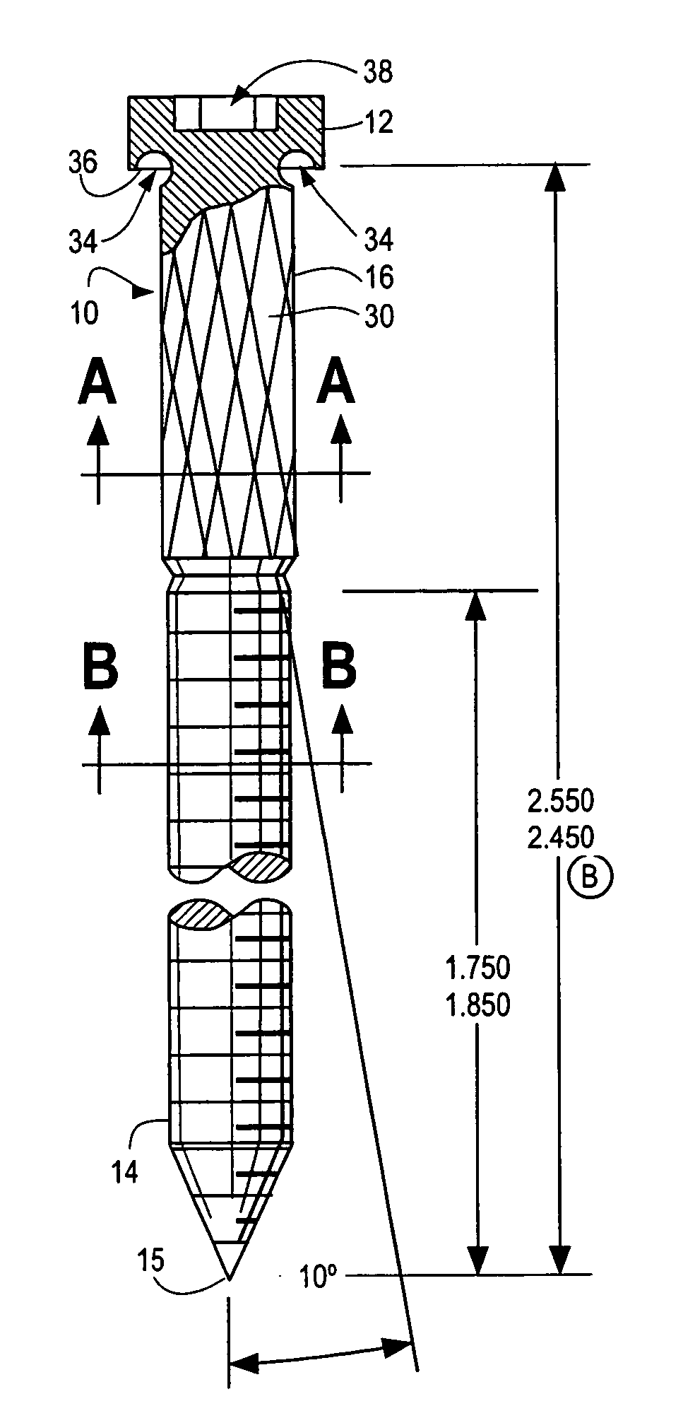
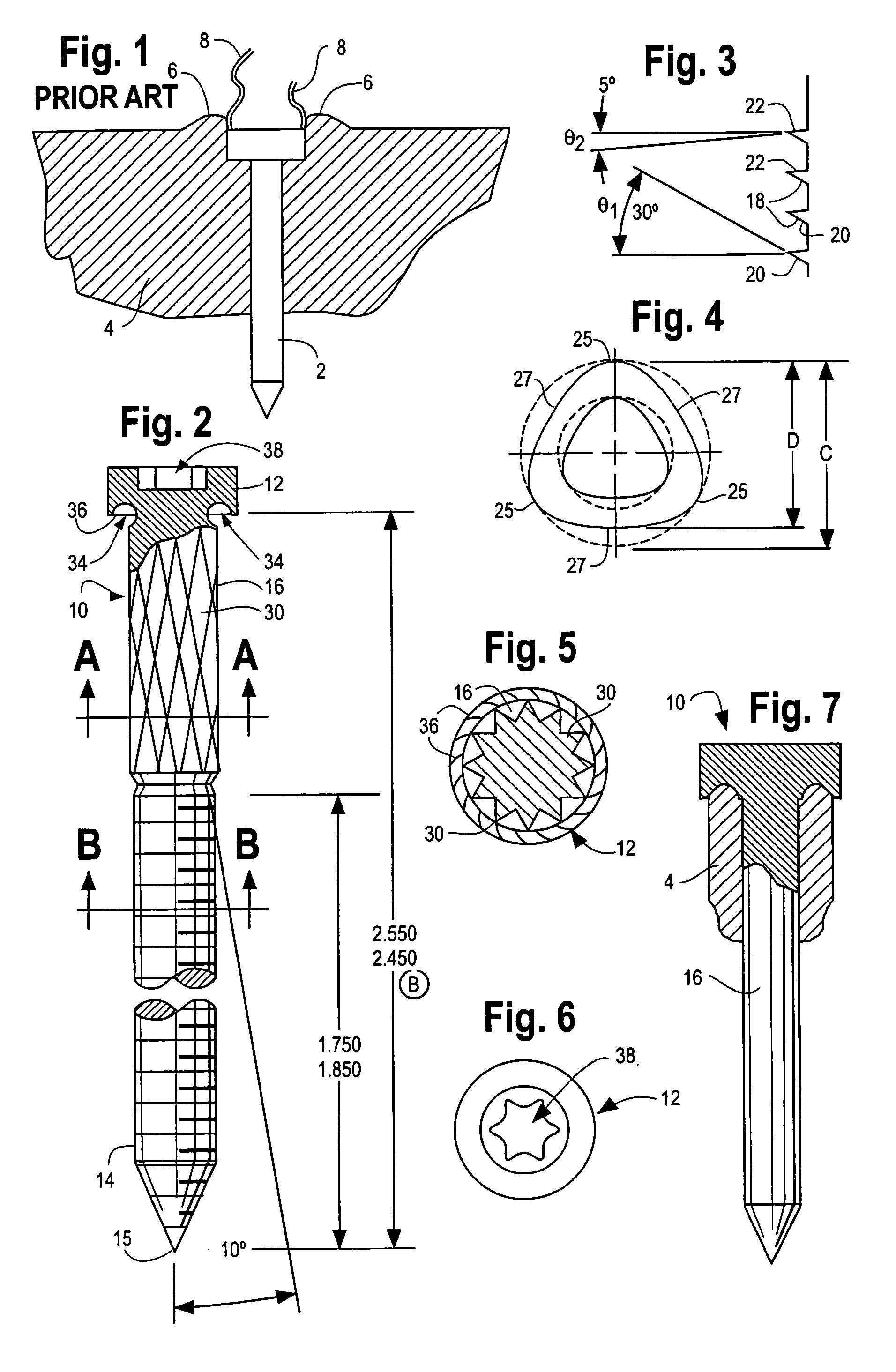
[0018] A screw 10 in accordance with the present invention, as shown in FIG. 2, for use with a composite lumber member or a conventional wood member includes a head 12, a threaded portion 14 that extends to adjacent a pointed end 15 of the screw 10; and a cutter portion 16 that is disposed between the head 12 and the threaded portion 14 of the screw. The cutter portion 16 of the screw 10 has a disruptive surface, as discussed in detail below, that cuts composite material away from a composite lumber member as the screw is driven into the composite member so as to prevent a mound of composite material from being formed about the head of the screw when the screw is set into the composite member. As such, no irregularities are formed in the surface of a composite lumber member when the screw 10 of the present invention is driven into the member.

[0019] In a preferred embodiment, the threaded portion 14 of the screw 10 includes one or more helical threads that extend from the bottom of ...


PUM


Abstract

A screw for use in a composite lumber member or a wood member has at least one disruptive surface that cuts composite material away from the composite lumber member as the screw is driven into the member to prevent a mound and / or strings from being formed that are attached to the composite lumber member when the screw is set therein. The screw may be used with conventional wood members wherein the screw of the present invention provides increased clamping when driven into a wood member to fasten the wood member to a support member or the like.

Description

CROSS-REFERENCE TO RELATED APPLICATIONS [0001] N / A STATEMENT REGARDING FEDERALLY SPONSORED RESEARCH OR DEVELOPMENT [0002] N / A TECHNICAL FIELD [0003] The present invention is directed to a screw for use with a composite lumber as well as wood and more particularly, to such a screw that prevents a mound of composite material from forming about the screw head when the screw is driven into a composite lumber member and which further provides increased clamping when the screw is inserted into a wood member to fasten the wood member to a support member. BACKGROUND OF THE INVENTION [0004] Composite lumber is a new type of lumber that is formed of a composite material that typically includes wood fibers, such as sawdust, a plastic and an adhesive materials, such as glue, to bond the composite materials together to form a composite lumber member, such as a plank. Composite lumber is often used in outdoor decks because of its increased durability as compared to conventional wood planks. Known...

Claims


Application Information

Patent Timeline
Patent Type & Authority Applications(United States)
IPC IPC(8): F16B35/06
CPCF16B33/02F16B35/065
Inventor ROMANO, MARKDEHAITRE, LON
Owner ROMANO MARK
Why Eureka
Try Eureka