Electronic control unit

Active Publication Date: 2007-03-29
JTEKT CORP
View PDF13 Cites 41 Cited by
  • Summary
  • Abstract
  • Description
  • Claims
  • Application Information

AI Technical Summary

Benefits of technology

[0006] Accordingly, it is an objective of the present invention to provide an electronic cont

Problems solved by technology

More specifically, if the electronic control unit is installed at a position where the casing is likely to be soaked, or completely immersed, in water in certain traveling states of the vehicle, the water resistance of the typical waterproof casing may be insufficient.
However, the portion in which the connector terminal

Method used


Image

  • Electronic control unit
  • Electronic control unit
  • Electronic control unit

Examples


first embodiment

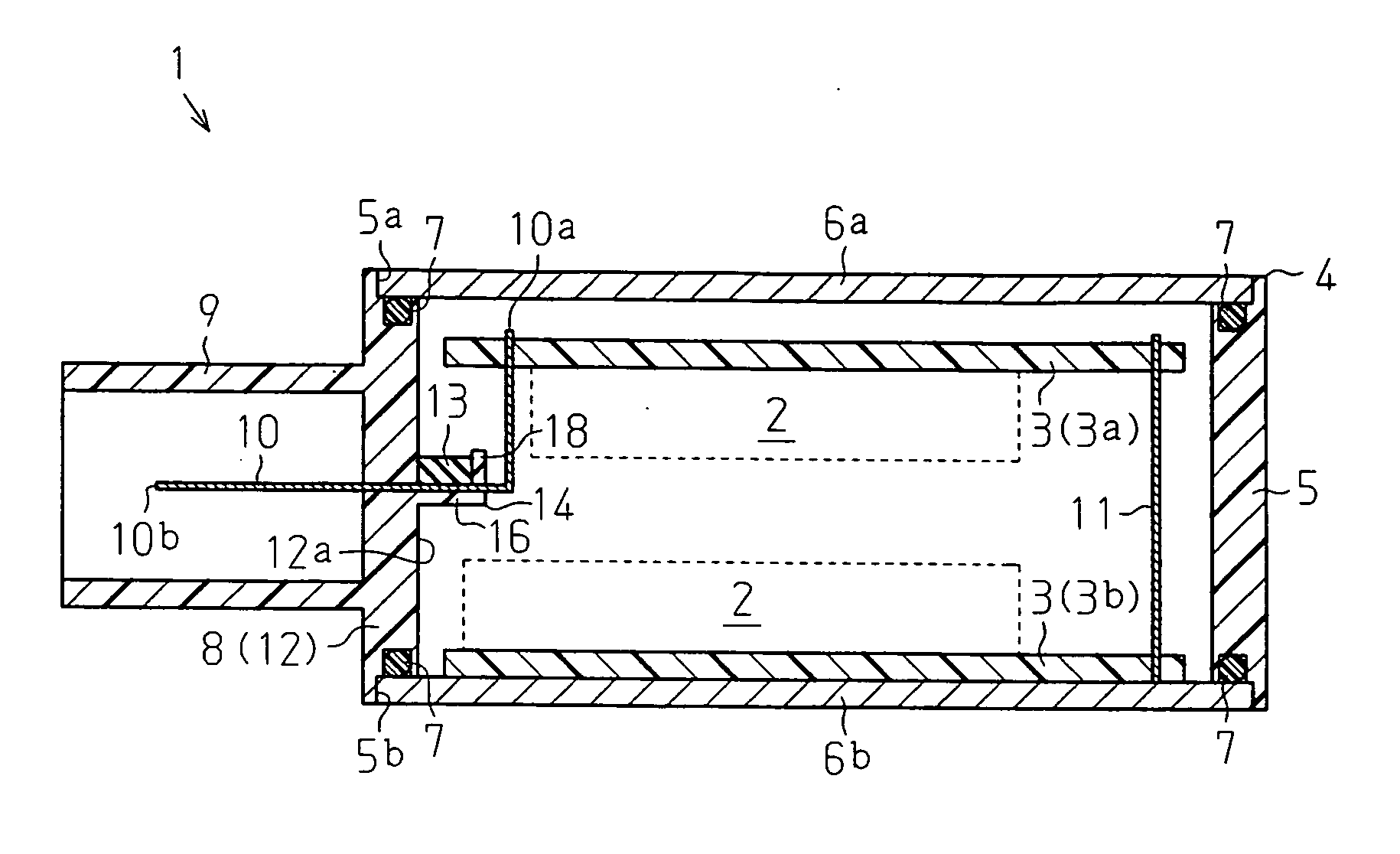
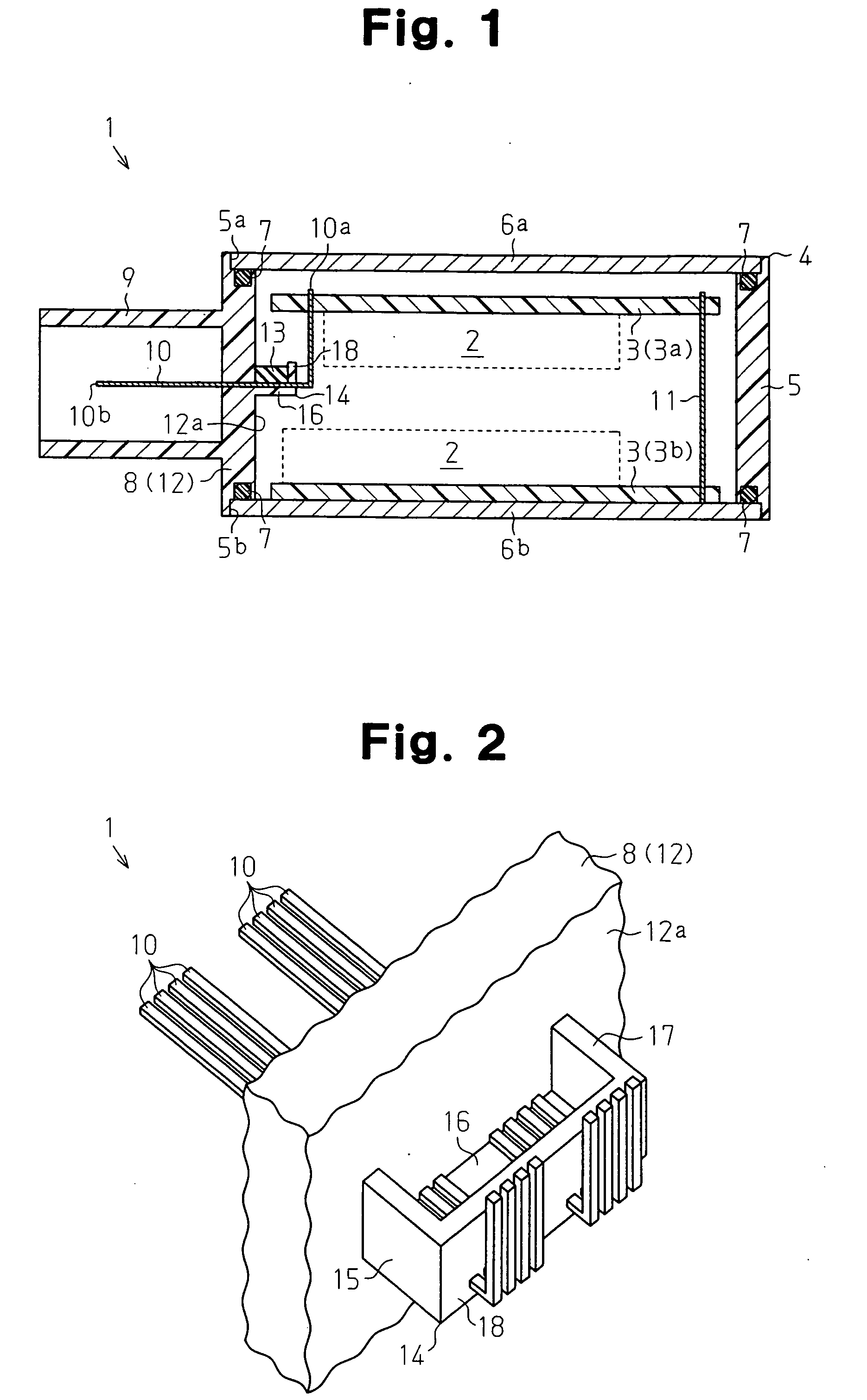
[0017] The electronic circuit substrate 3 has a double-layered structure formed by two substrate sections 3a, 3b that are connected together through a connection terminal 11. The substrate sections 3a, 3b extend parallel with the lids 6a, 6b of the casing 4. A portion of each connector terminal 10 in the vicinity of the end 10a, which is located in the casing 4, is bent toward the substrate section 3a in an L-shaped manner. In this manner, the connector terminals 10 are connected to the substrate section 3a. In the first embodiment, the lids 6a, 6b of the casing 4 are made of metal exhibiting increased heat radiation performance. Accordingly, when held in contact with the corresponding substrate section 3a, 3b, each lid 6a, 6b functions as a heat sink that releases heat from the electronic components 2, which are mounted on the substrate sections 3a, 3b, to the exterior of the casing 4.

[0018] In the first embodiment, referring to FIGS. 1 and 2, a retainer portion 14 is provided at a...

second embodiment

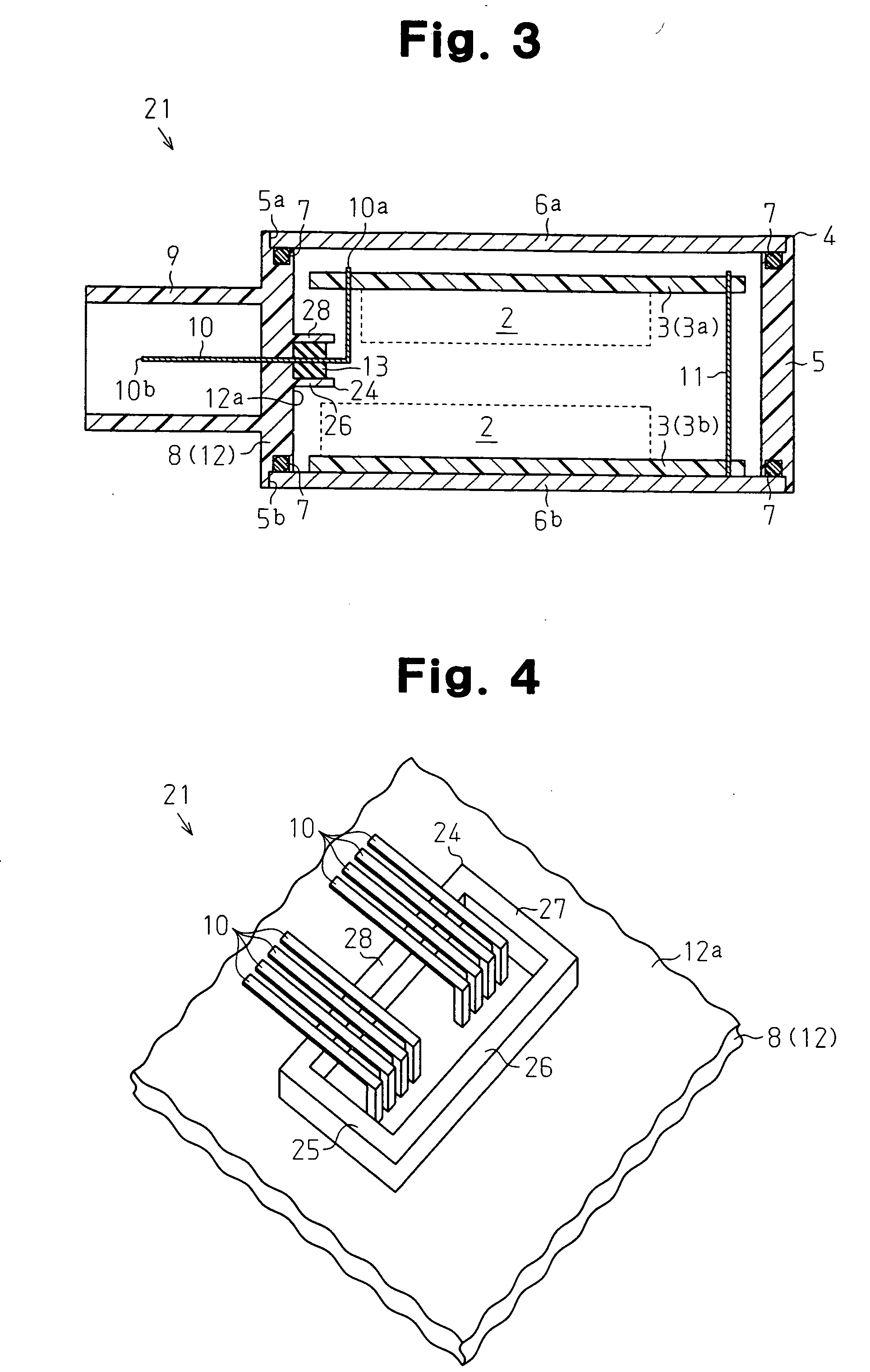
[0025] The second embodiment has the following advantages.

[0026] (1) The inner peripheral surface of the retainer portion 24 does not contact the connector terminals 10. This prevents a small empty gap from being provided in a contact portion between any one of the connector terminals 10 and the inner peripheral surface of the retainer portion 24. This ensures improved resistance to water of the electronic control unit 21.

[0027] (2) The retainer portion 24 has the side walls 25 to 28 that project from the inner side 12a of the connector terminal support wall 12 in the extending direction of each connector terminal 10. The side walls 25 to 28 extend substantially parallel with the connector terminals 10 projecting into the casing 4 and are arranged around the connector terminals 10. The opening of the retainer portion 24 faces in the extending direction of each connector terminal 10. The connector terminals 10 are thus easily prevented from contacting the inner peripheral surface of...


PUM


Abstract

An electronic control unit includes an electronic circuit substrate and a casing that accommodates the electronic circuit substrate. A plurality of electronic components are mounted on the electronic circuit substrate. A plurality of connector terminals extend through a side wall of the casing for electrically connecting the electronic circuit substrate to external wires. A retainer portion capable of retaining liquid seal agent is arranged at an inner side of the wall through which the connector terminals extend.

Description

CROSS-REFERENCE TO RELATED APPLICATIONS [0001] This application is based upon and claims the benefit of priority from prior Japanese Patent Application No. 2005-277337, filed on Sep. 26, 2005, the entire contents of which are incorporated herein by reference. BACKGROUND OF THE INVENTION [0002] The present invention relates to an electronic control unit. [0003] A typical electronic control unit includes a casing and an electronic circuit substrate accommodated in the casing. The casing is waterproofed in various ways (see, for example, Japanese Laid-Open Patent Publication No. 2005-150633). Nonetheless, if the electronic control unit is installed in, for example, a vehicle having limited space, it is necessary to further improve the resistance to water of the casing for space efficiency in the vehicle. [0004] More specifically, if the electronic control unit is installed at a position where the casing is likely to be soaked, or completely immersed, in water in certain traveling state...

Claims


Application Information

Patent Timeline
IPC IPC(8): H05K1/00
CPCB60R16/0239H01R13/5202H05K5/069H05K5/0043H01R13/521Y10S439/936
Inventor INAGAKI, TATSUYAKOHNO, TOSHIO
Owner JTEKT CORP
Why Eureka
Try Eureka