Passive ventilation control system

a passive ventilation and control system technology, applied in ventilation systems, lighting and heating apparatus, heating types, etc., can solve the problems of not being able to effectively ventilate the whole building, the remaining area of the house is usually not passively ventilated, and the stack vents are relatively small

Active Publication Date: 2007-03-29
DANIELS II WILLIAM B +1
View PDF30 Cites 158 Cited by
  • Summary
  • Abstract
  • Description
  • Claims
  • Application Information

AI Technical Summary

Benefits of technology

[0013] In accordance with another embodiment, a roof vent is provided. The roof vent includes a vent member, a vent door, and an actuator. The vent member includes an opening and is configured to be secured at an aperture in a roof so that the opening permits airflow through the aperture and the opening between regions above and below the roof. The vent door is operatively connected to the vent member. The vent door has an open position in which the vent door permits airflow through the opening and a closed position in which the vent door substantially prevents airflow through the opening. The actuator is configured to move the vent door between the open and closed positions based on ambient temperature.

Problems solved by technology

While this permits ventilation of the attic, the remainder of the house is usually not passively ventilated because the attic is closed off from the rest of the house.
A practical drawback of passive stack ventilation is that stack vents are relatively small.
The stack vents typically cannot effectively ventilate the whole building unless the building is very small or unless many stack vents are provided.
The small size of a stack vent or pipe makes it difficult for atmospheric pressure to produce significant airflow through the vents, regardless of whether they extend upward through the roof, outward through the walls, or downward through the floor and then outward and upward through the ground outside of the building.

Method used


Image

  • Passive ventilation control system
  • Passive ventilation control system
  • Passive ventilation control system

Examples


Embodiment Construction

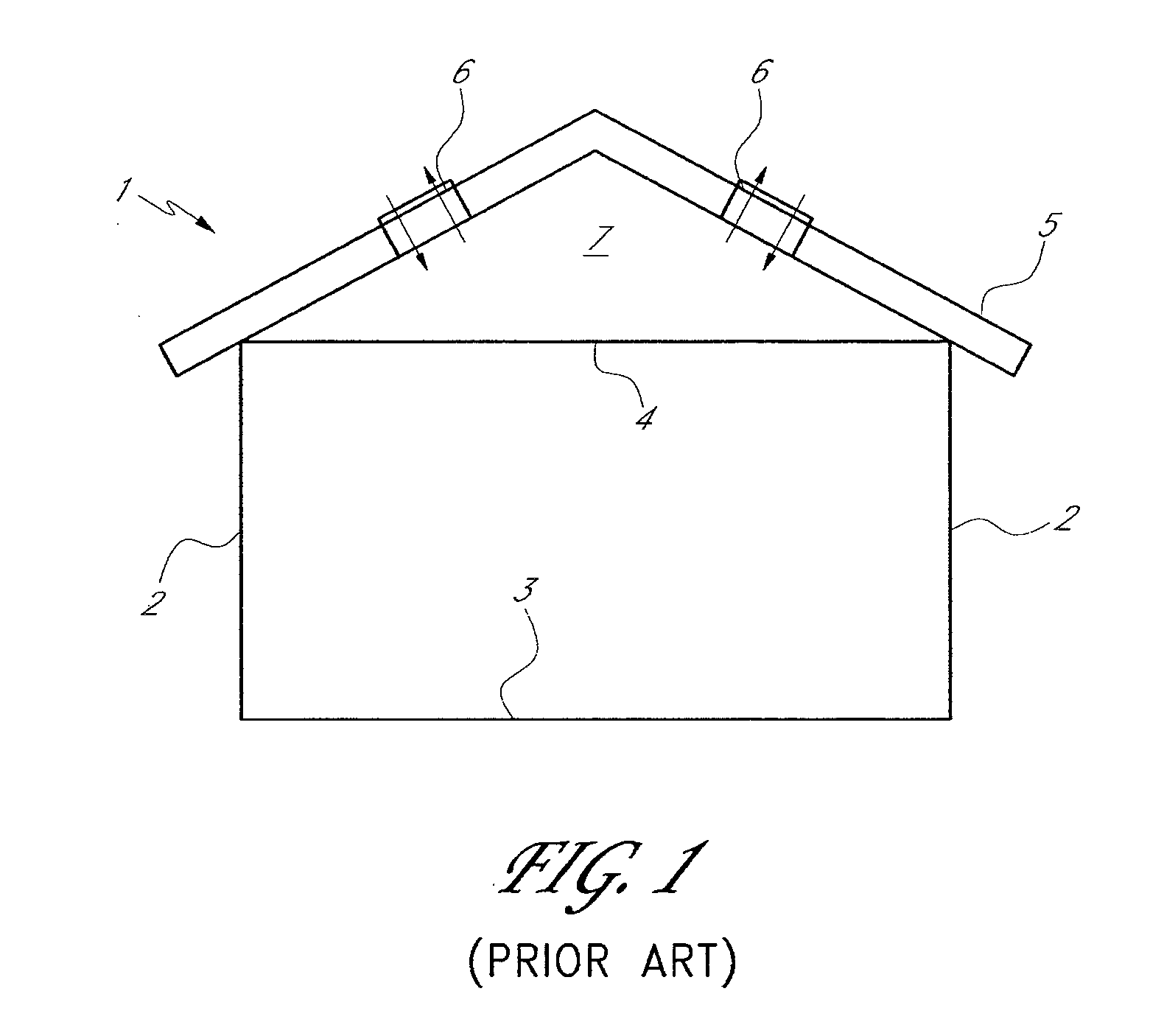
[0041] Conventional systems for passive ventilation of buildings are limited in their ability to adequately ventilate a building. For example, while passive stack ventilation provides some passive ventilation of a building, it has been restricted to kitchens, bathrooms, and / or laundry rooms. While the stack vents may extend through other (non-pollutant) rooms of the building, they do not permit venting of such rooms because the stack vents do not fluidly communicate with such rooms. Also, passive stack ventilation is somewhat restricted because it involves the flow of air through elongated stack vents, which sometimes include turns and irregular configurations. Adequate ventilation through the stack vents is often dependent upon suction at the upper ends of the stack vents, due to a venturi effect caused by winds above the building. The stack vents inhibit the building from “breathing” freely. Thus, buildings having stack vents, perhaps in combination with vents in the floor or exte...


PUM


Abstract

A passive ventilation control system and method. The system includes passive vents throughout a building. The vents may be arranged in multiple sets, with each set being substantially vertically aligned through multiple floors or the entire height of the building. Sensors are positioned inside and/or outside the building for sensing different environmental parameters or atmospheric conditions. The sensors send signals to a controller, which automatically adjusts airflow through the vents in response to the signals from the sensors.

Description

REFERENCE TO RELATED APPLICATIONS [0001] This application claims the benefit of U.S. Provisional Patent Application No. 60 / 721,673, filed on Sep. 23, 2005 and the benefit of U.S. Provisional Patent Application No. 60 / 795,905, filed on Apr. 27, 2006.BACKGROUND OF THE INVENTION [0002] 1. Field of the Invention [0003] This invention relates generally to building ventilation and specifically to systems and methods for controlling passive ventilation. [0004] 2. Description of the Related Art [0005] Many buildings are ventilated with so-called “active ventilation” or “mechanical ventilation” apparatus, which typically involves the use of mechanical devices such as fans, air conditioners, etc., which create a forced flow of air through various ducts and vents of the building. In many cases, it is desirable to avoid active ventilation in order to reduce energy requirements. [0006] So-called “passive ventilation” involves an arrangement of vents within a building, without mechanical devices ...

Claims


Application Information

Patent Timeline
Patent Type & Authority Applications(United States)
IPC IPC(8): F24F7/02F24F7/003
CPCE05Y2400/40E05Y2400/42E05Y2800/21F24F7/02F24F11/0001F24F11/0012E05F15/71F24F11/0017F24F2007/004Y02B30/78E05Y2201/43E05Y2800/67E05F15/60F24F11/0015F24F11/30F24F2110/10F24F2110/20F24F2110/50Y02B30/70F24F11/70F24F11/523F24F11/56F24F7/003
Inventor DANIELS, WILLIAM B. IIO'HAGIN, CAROLINA
Owner DANIELS II WILLIAM B
Why Eureka
Try Eureka