Eluting, implantable medical device

a medical device and implantable technology, applied in the field of medical devices, can solve the problems of balloon-expandable stents, balloon-expandable stents, risky surgery, etc., and achieve the effect of minimizing fracturing the ceramic layer and less strain

Inactive Publication Date: 2007-03-29
COOK INC
View PDF37 Cites 161 Cited by
  • Summary
  • Abstract
  • Description
  • Claims
  • Application Information

AI Technical Summary

Benefits of technology

The patent describes methods for creating intraluminal devices with porous structures that can carry drugs or other active substances. These techniques include depositing a thin metallic film on a foam structure using chemical vaporization, sintering metal powder, or applying a ceramic layer selectively to areas where it will have minimal stress while leaving others exposed to prevent cracking. Overall, this technology allows for the fabrication of implantable medical devices with controlled release capabilities.

Problems solved by technology

The technical problem addressed in this patent text is how to effectively combine biodegradable stents with other interlaminal devices, such as paclitaxel, sirolimus, and everolimus, while avoiding issues related to traditional methods of coating such as wear off and incomplete release control. Current techniques involve applying a bioactive substance directly to the surface of the device or creating pits or reservoirs inside the device to hold the substance. These challenges include difficulty in controlling the release rate and ensuring effective delivery of the bioactive substance to the targeted areas.

Method used


Image

  • Eluting, implantable medical device
  • Eluting, implantable medical device
  • Eluting, implantable medical device

Examples


Embodiment Construction

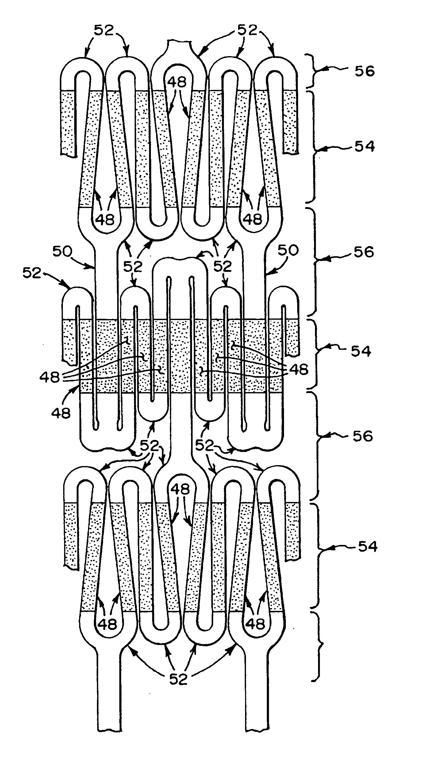
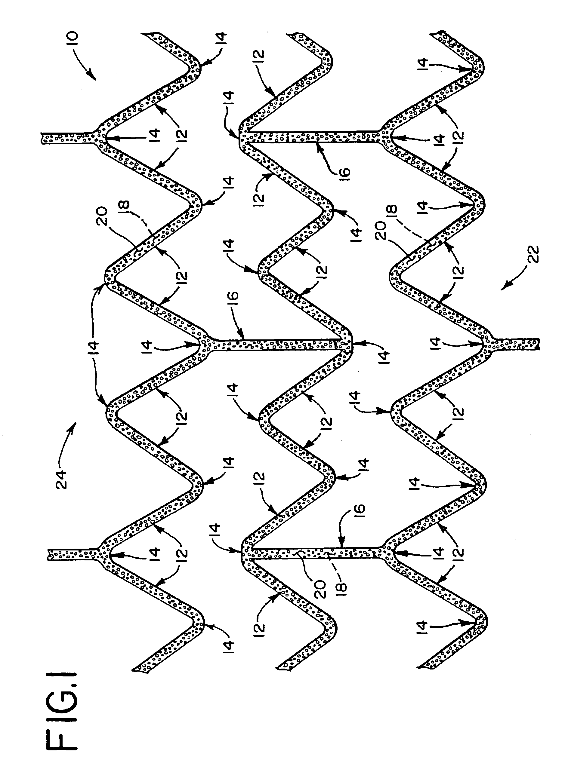
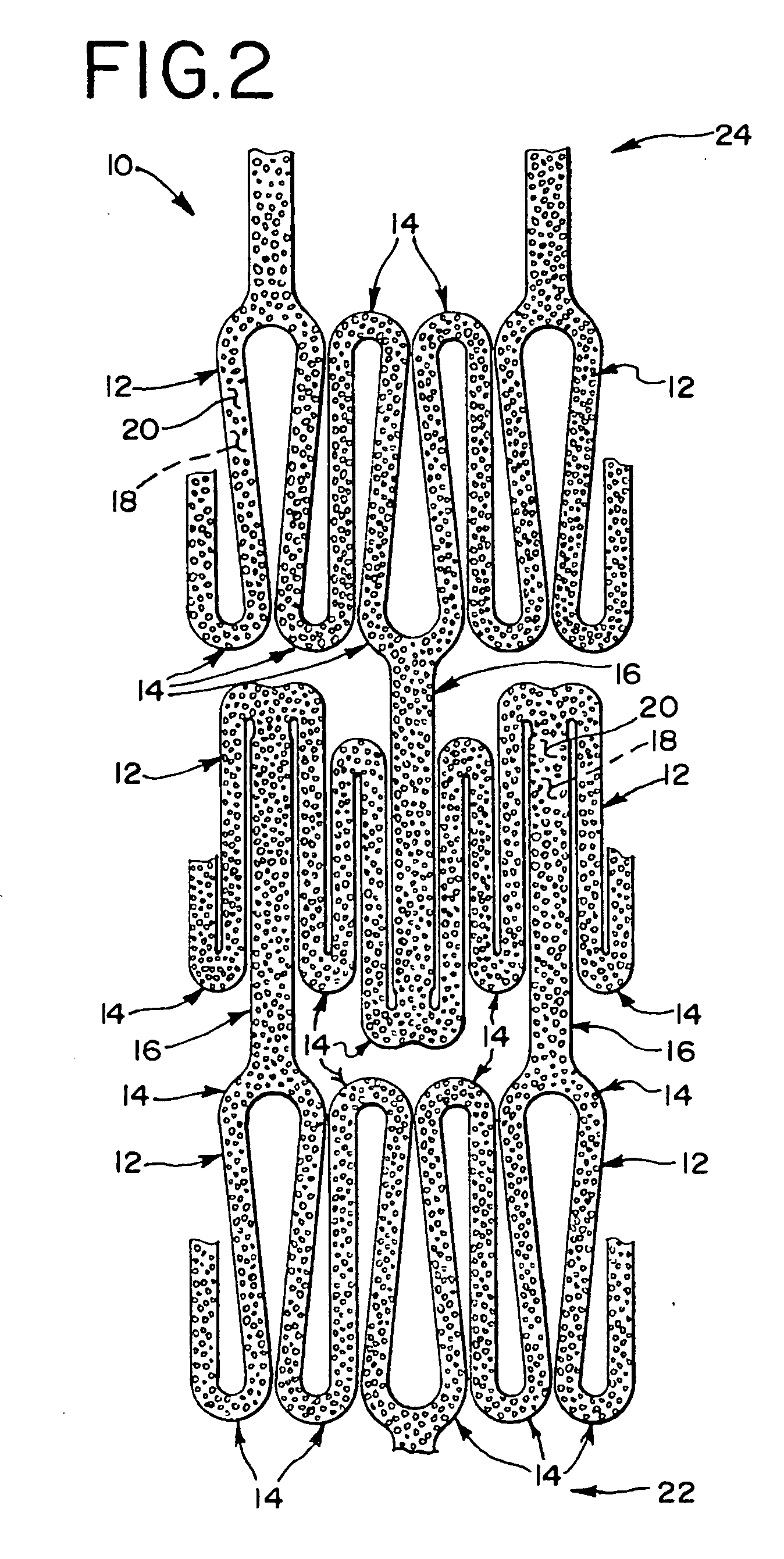
[0098] Referring now to the drawings, and particularly to FIGS. 1 and 2, an endoluminal stent 10 is shown. The structure of the stent 10 that is shown is only one example of the type of stent structure that may be used and many other stent structures known in the art may also be used. The stent 10 is made from a series of angular struts 12 interconnected with bends 14. Longitudinal struts 16 may also be used to interconnect the bends 14 and angular struts 12, thereby forming a cylindrical structure with an inner surface 18, an outer surface 20, a proximal end 22 and a distal end 24. Preferably, the stent 10 is expandable between a collapsed configuration as shown in FIG. 2 and an expanded configuration as shown in FIG. 1.

[0099] Typically, the collapsed configuration is suitable for introducing the stent 10 into a vessel of a patient and passing the stent 10 through the vessel to a portion to be treated. This may be achieved using a variety of different procedures which may be adapt...


PUM


Abstract

An intraluminal device is provided with a porous structure. The porous structure may be loaded with a bioactive substance to treat surrounding tissues after the intraluminal device has been implanted. The porous structure may be made by depositing a metal film on a foam structure using chemical vapor deposition. Porous structures may also be made by sintering or applying a ceramic layer to the intraluminal device. An intraluminal device is also provided with a ceramic material applied to generally straight portions of the device structure but not to portions adapted to bend. One advantage is that the ceramic material is less likely to fracture since it is applied to regions that experience less strain.

Description


Claims


Application Information

Patent Timeline
Owner COOK INC
Why Eureka
Try Eureka