Bag-filling packaging machine

a packaging machine and bag technology, applied in the field of bag-filling packaging machines, can solve the problems of inability to insert another member inside the bag, inability to carry out packaging operations, and impaired degree of freedom of packaging operations, and achieve the effect of stable fashion

Inactive Publication Date: 2007-04-05
TOYO JIDOKI CO LTD
View PDF9 Cites 39 Cited by
  • Summary
  • Abstract
  • Description
  • Claims
  • Application Information

AI Technical Summary

Benefits of technology

[0011] Accordingly, the object of the present invention is to provide a bag-filling packaging machine that performs gas replacement assuredly and in a stable fashion.
[0012] More specifically, the object of the present invention is to provide a bag-filling packaging machine that includes a plurality of pairs of 
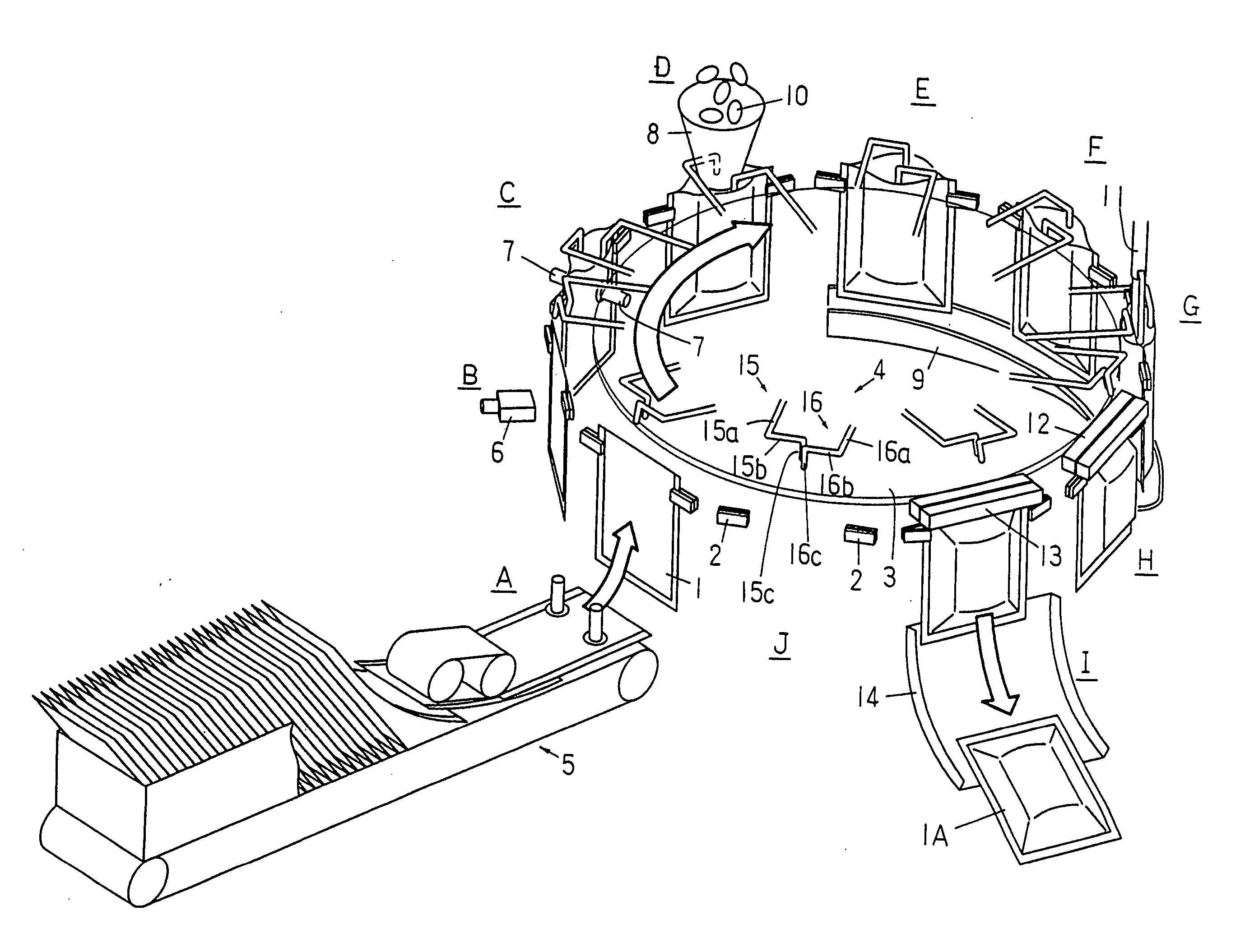
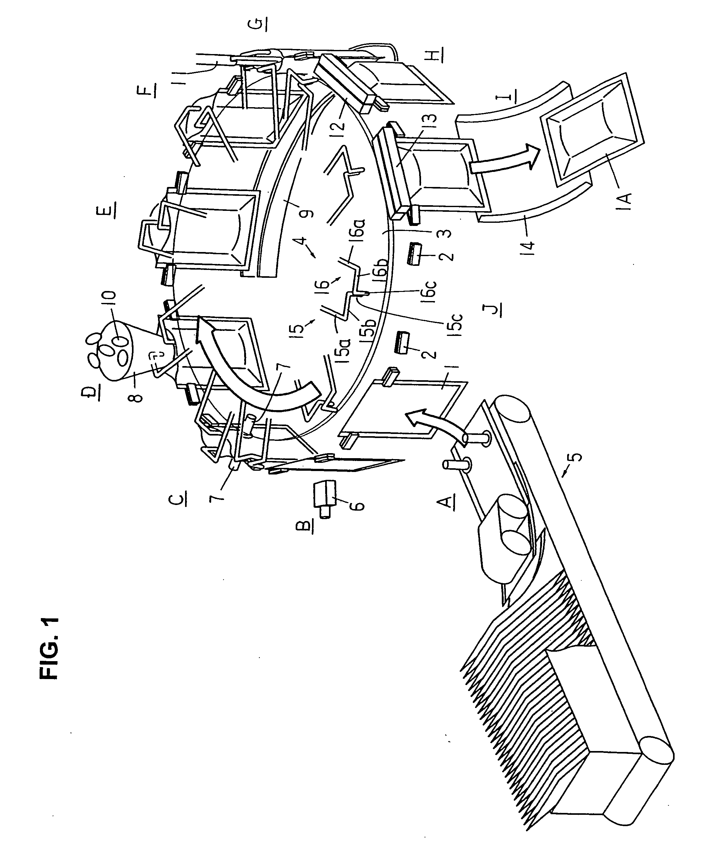
grippers for gripping the edges of both sides of supplied bags and suspendingly holding the bags, at equal intervals along a horizontal endless bag conveyance path, so as to revolvingly move the pairs of grippers in one direction, either continuously or intermittently in each of the such intervals, and so as to successively perform various packaging operations, such as opening the bag mouths, filling the bags with the contents to be packaged, and sealing the bag mouths, on the bags held by the pairs of grippers; and in this type of packaging machine, the present invention assuredly and stably performs gas replacement, without compromising production efficiency, and without impairing the degree of freedom in the packaging operations.
[0024] As seen from the above, in the bag-filling packaging machine of the present invention, guide members are provided so as to correspond respectively to the pairs of grippers, the guide members are designed so that they not only function to keep the bag mouth opened but also function as gas replacement nozzles, the gas replacement time period is set to be long, over which entire time period it is possible to continuously perform blow-in of an inactive gas or the like into the bags and, as necessary, air removal and gas replacement for the bags is performed assuredly and stably for all of the bags. With the guide members that function as bag mouth opener and also function as gas replacement nozzles, gas replacement can be performed without making the relevant structures overly complex.
[0026] In addition, in the present invention, the guide member connected to the gas supply source can be designed so that the gas blow-in pressure is adjustable. Thus, the blow-in volume during gas blowing into the bags can be adjusted. Accordingly, gas blow-in and air removal (vacuuming) can be appropriately combined, or the gas blow-in intensity can be suitably altered, so that gas replacement can be performed in an optimal pattern depending upon the type of the contents to be filled or upon the size of bags.
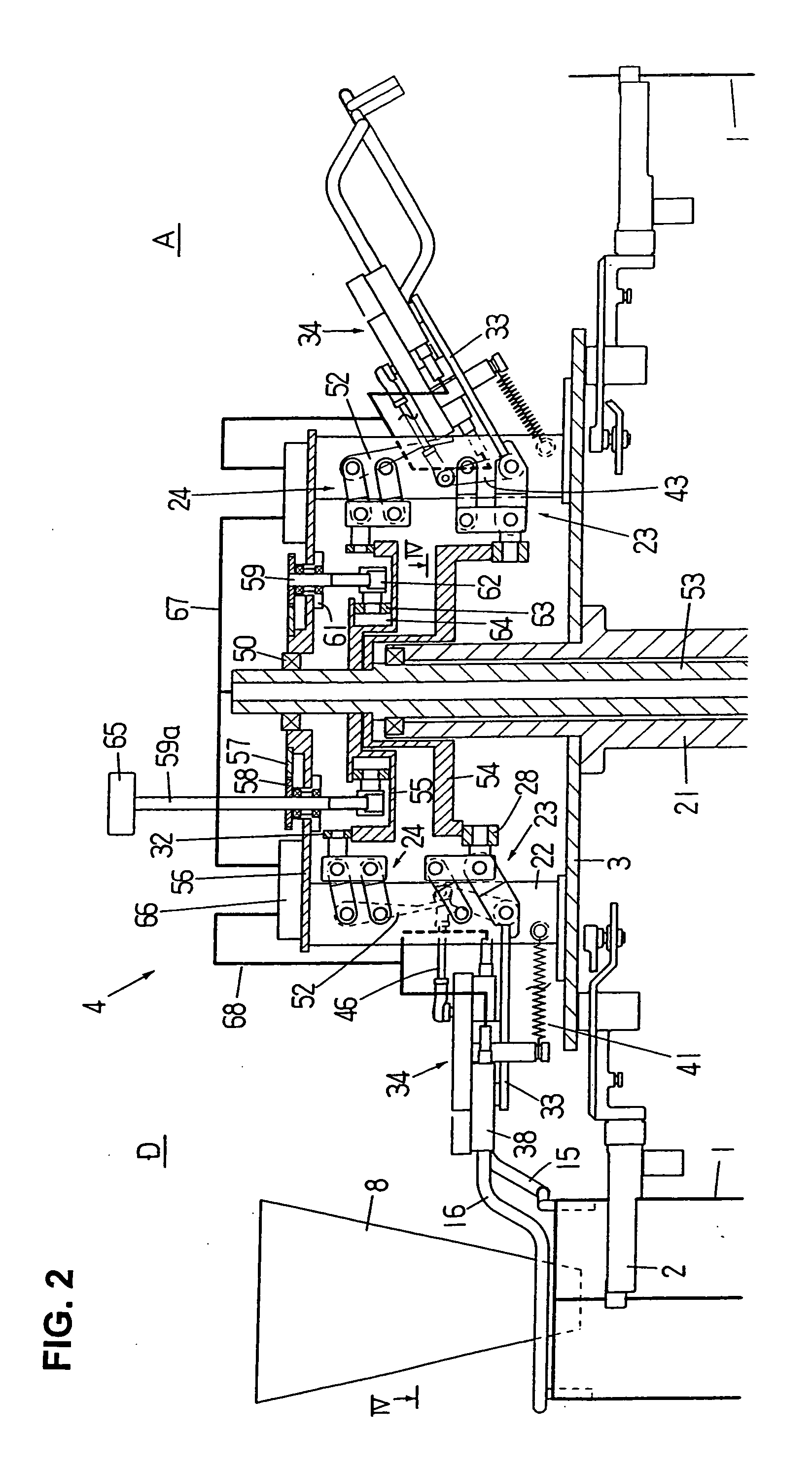
[0027] In the present invention, the guide portions of the pair of (or two) guide members are opened and closed (separation-proximity) in the interior of each bag, and the positions of the guide portions are preferably set so that, when in the closed state, the two guide portions of the pair of (or two) guide members are positioned close to each other and aligned in the bag width direction substantially at the center of the bag mouth. As a result, the space occupied by the two guide portions in the direction perpendicular to the bag width direction is small or narrow; and as a consequence, when the distance between the gripper pair (or the distance between two grippers) is widened and the bag mouth is thus tensioned (pulled) laterally to the left and right with the guide members in the bag, the opening in the bag mouth becomes very narrow; as a result, the inflow of outside air into the bag and the outflow of gas from the bag interior are limited, and thus improved gas replacement can be executed.
[0029] In the present invention, further, both guide portions which are closed inside a bag are shifted in the bag width direction from the bag width center position and thus they are not exactly at the center of the bag mouth in terms of the width of the bag. Accordingly, when the two guide portions are open (separation) or close (proximity), when they are moved linearly in a direction perpendicular to the bag width direction as in the conventional opening members, the opened bag mouth would be distorted in the shape of a parallelogram, and such distortion would be relatively larger for the bag is small in width. In the present invention, in cases that the guide portions are close to each other, side by side, in the bag width direction at substantially the center of the opened bag mouth and then moved in mutually opposite directions along the circular arc-shaped paths, respectively, in a horizontal plane, and such circular arc-shaped paths are established so that both of them, in the middle, approach the center in the bag width direction, then when the bag width size is small, the movement distance of the guide portions is small, and the opening guide portions will approach the vicinity of the bag width center along the circular arc-shaped paths of the guide portion, and as a result, the distortion in the opened bag mouth will be suppressed. When the bag width size is large, the guide movement distance is large, and the opening guide portions, after approaching the vicinity of the bag width center, are again moved away from the vicinity of the bag width center along the circular arc-shaped paths. Thus, though distortion might appear in the opened bag mouth, it will not be much of a problem.

Problems solved by technology

Also, the degree of freedom of packaging operations is impaired, and it is thus not possible, for example, to insert another member inside a bag after the bag has been filled.
However, the hoppers get in the way in doing such an operation, and it is thus not possible to insert another member inside a bag once a bag has been filled.
As a result, the assurance and stability of the gas replacement are somewhat inferior.

Method used


Image

  • Bag-filling packaging machine
  • Bag-filling packaging machine
  • Bag-filling packaging machine

Examples


Embodiment Construction

[0044] The bag-filling packaging machine of the present invention will be described below in detail with reference to FIG. 1 to 13.

[0045] In the rotary type bag-filling packaging machine shown in FIG. 1, a plurality of pairs of grippers 2 for respectively gripping the left and right edge on both sides of a bag 1 and suspending that bag are provided at equal intervals about the periphery of a round table 3 that revolves intermittently (the arrow indicating the turning direction). In addition, guide mechanisms 4 (only the guide members 15 and 16 thereof are shown in FIG. 1) for keeping the bag mouth opened are provided on the table 3 so as to correspond, respectively, to each pair of grippers 2.

[0046] At process positions (A to J) about the periphery of the table 3 are provided: a conveyor magazine type bag feeder 5 at position A; a printing device (a printer 6 only is shown) at position B; a bag mouth opener (suction plates 7 only are shown) at position C; a device for supplying th...


PUM


Abstract

A bag-filling packaging machine in which supplied bags 1 are gripped by pairs of grippers 2 disposed on the periphery of an intermittently turning round table 3, and the bags, at stopping positions, are successively subjected to prescribed packaging operations with the gas inside the bags being replaced during that process, wherein a pair of guide members 15 and 16 for keeping the bag mouth opened is provided on the table 3 in correspondence with each of the gripper pair, and guide members 15 and 16 are connected to an inactive gas supply source and have gas blow-out ports at the tip ends that are inserted inside the bags, thus allowing the guide members 15 and 16 to not only keep the bag mouth opened but also function as gas blow-in nozzles.

Description

BACKGROUND OF THE INVENTION [0001] 1. Field of the Invention [0002] The present invention relates to a bag-filling packaging machine that includes pairs of grippers for holding supplied bags and holding them in a prescribed attitude, successively performs various packaging operations, including opening the bag mouths, filling the bags with the contents to be packaged, and sealing the bag mouths, and further replaces the gas inside the bags during the process. [0003] 2. Description of the Related Art [0004] Bag-filling packaging machines generally perform, during the packaging process, the insertion of a gas blow-in nozzle into the bags through the bag mouths, and the replacement of the air inside the bags with an inactive gas (such as nitrogen gas, for example). There are three major systems that are currently known to execute these tasks. [0005] (1) Stationary System: This system is typically employed in an intermittently moving type of rotary bag-filling packaging machine. In this...

Claims


Application Information

Patent Timeline
Patent Type & Authority Applications(United States)
IPC IPC(8): B65B31/00B65B43/26
CPCB65B43/36B65B43/465B65B31/041B65B43/14B65B43/34B65B1/06B65B5/061
Inventor KOGA, SHOICHIKAWAMURA, KENJI
Owner TOYO JIDOKI CO LTD
Why Eureka
Try Eureka