Magnetostrictive torque sensor and electrically powered steering apparatus using same

a technology of magnetostrictive torque and torque sensor, which is applied in the direction of electrical steering, piezoelectric/electrostrictive/magnetostrictive devices, instruments, etc., can solve the problems of misalignment and unpleasant sensation of the driver in regard to steering responsiveness, and achieve the improvement of the sensitivity of the magnetostrictive torque sensor, the effect of satisfying the steering feel and increasing the tolerance of positional misalignment during the assembly of the sensor

Inactive Publication Date: 2007-04-05
HONDA MOTOR CO LTD
View PDF6 Cites 45 Cited by
  • Summary
  • Abstract
  • Description
  • Claims
  • Application Information

AI Technical Summary

Benefits of technology

[0019] The magnetostrictive torque sensor described above is used as the steering torque sensor provided to the steering shaft that bears the steering force from the steering wheel. Based on the merits of the magnetostrictive torque sensor, it is possible to maintain a satisfactory steering feel in the electrically powered steering apparatus over a long period of time.
[0020] The axial width W1 of the magnetostrictive regions is set to have an optimum dimensional relationship with the axial width W2 of the sensor coils in a magnetostrictive torque sensor. Accordingly, the sensitivity of the magnetostrictive torque sensor can be improved, and the positional misalignment tolerances during assembly of the sensor can be increased. Therefore, tolerances are even easier to manage when the sensor apparatus is manufactured. Further-more, with an electrically powered steering apparatus configured using this magnetostrictive torque sensor, the rate of change in sensitivity of the magnetostrictive torque sensor can be adequately maintained and the steering feel of the electrically powered steering apparatus can be kept at a satisfactory level over a long period of time even in cases in which the axial positional relationship between the steering shaft and the sensor coils becomes misaligned in relative terms in subsequent use.

Problems solved by technology

Therefore, if the rate of change in sensitivity falls below 0.98, the driver may experience an unpleasant sensation in regard to steering responsiveness in cases in which the sensor is actually installed in an automobile or the like.
Particularly, when such a magnetostrictive torque sensor is used in an electrically powered steering apparatus of an automobile, it is undesirable for such positional misalignment to occur because the electrically powered steering apparatus creates an unpleasant sensation when operated.

Method used


Image

  • Magnetostrictive torque sensor and electrically powered steering apparatus using same
  • Magnetostrictive torque sensor and electrically powered steering apparatus using same
  • Magnetostrictive torque sensor and electrically powered steering apparatus using same

Examples


Embodiment Construction

[0031] Preferred embodiments of the present invention will now be described with reference to the accompanying drawings.

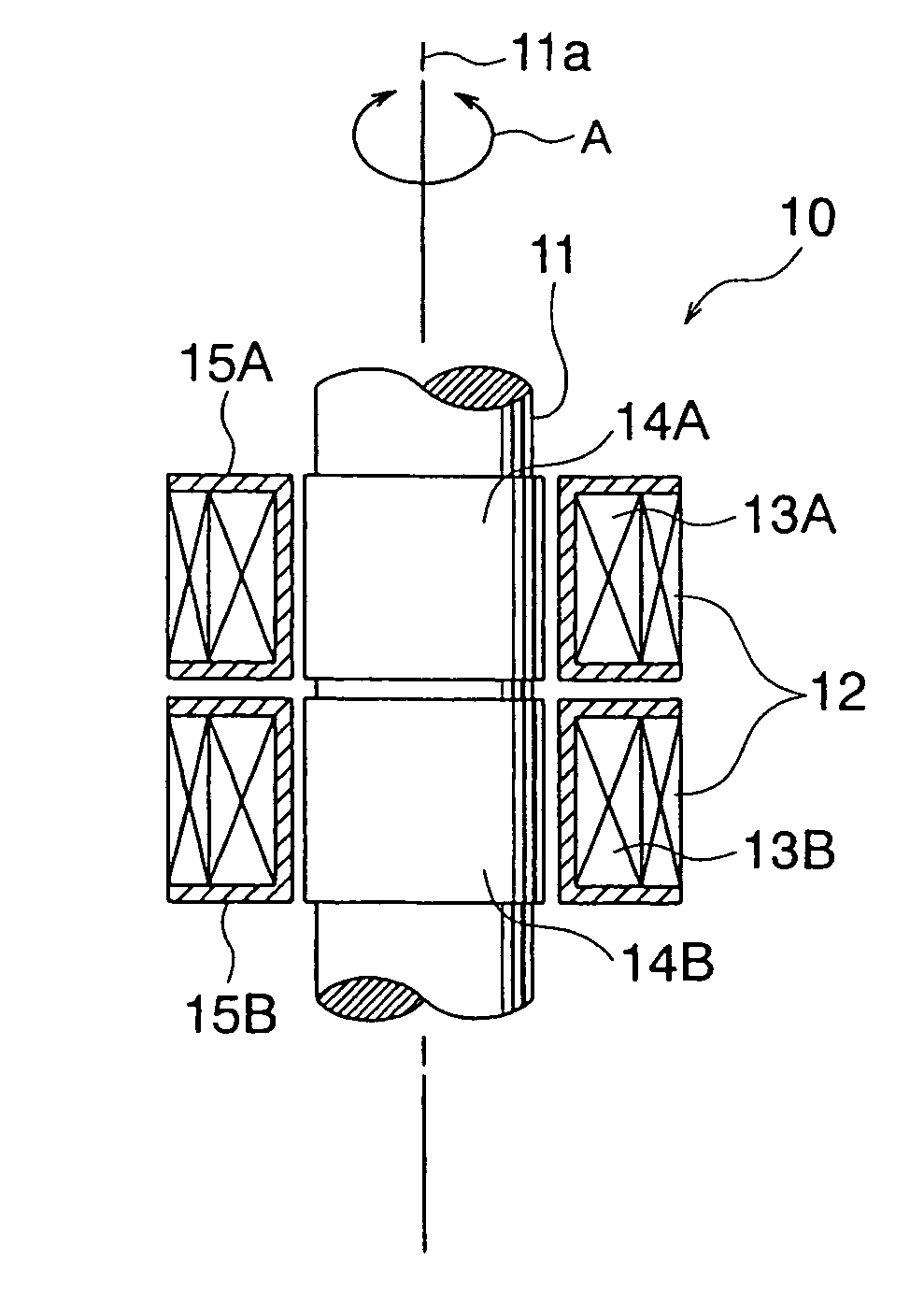
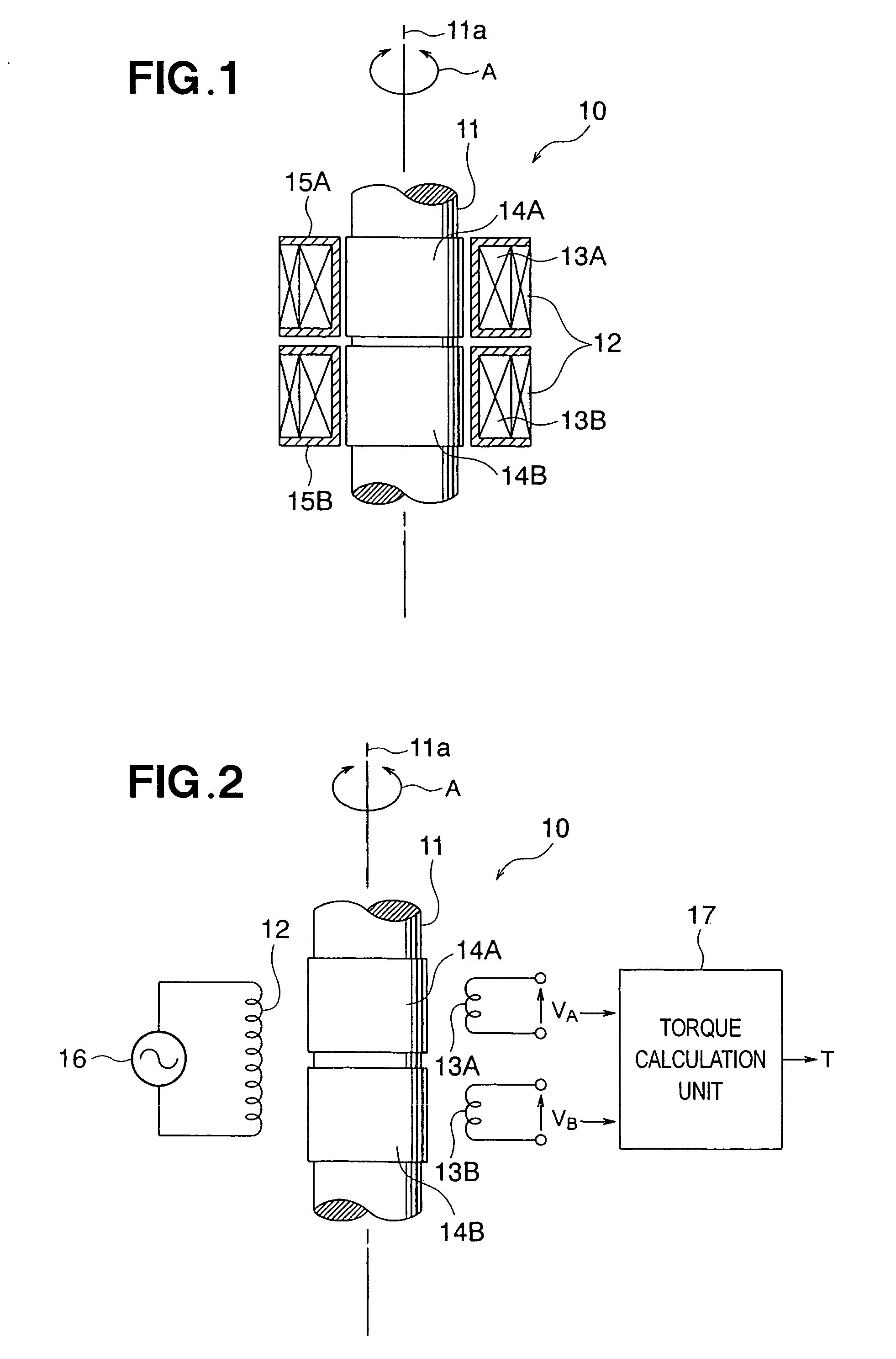
[0032] First, the configuration of the magnetostrictive torque sensor will be described with reference to FIGS. 1 through 3. FIGS. 1 through 3 show a structural example of the magnetostrictive torque sensor according to the present invention.

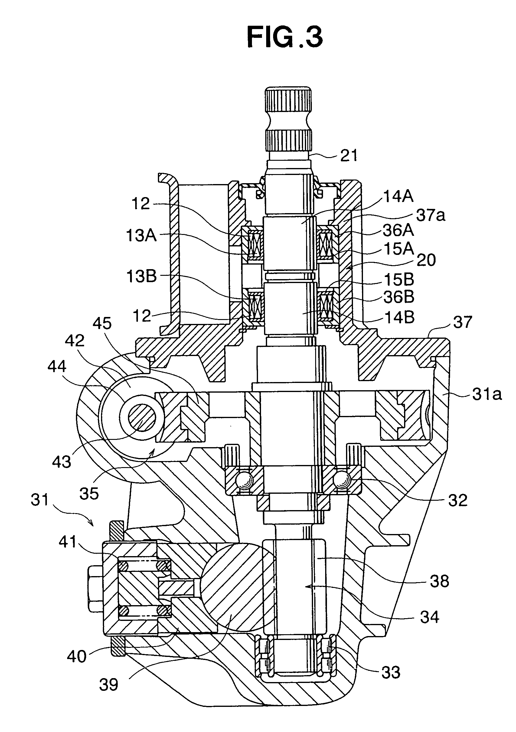
[0033] A magnetostrictive torque sensor 10 is configured from a rotating shaft 11, and one excitation coil 12 and two sensor coils 13A, 13B disposed around the periphery of the rotating shaft 11. For the sake of convenience in the description, the rotating shaft 11 is shown without the top and bottom parts in FIGS. 1 and 2. When the magnetostrictive torque sensor 10 is used as a steering torque sensor in an electrically powered steering apparatus of an automobile, the rotating shaft 11 constitutes part of the steering shaft. This state is shown in FIG. 3.

[0034] The rotating shaft 11 has a columnar rod shape and is subjected ...


PUM

PropertyMeasurementUnit
widthaaaaaaaaaa
magnetostrictiveaaaaaaaaaa
impedanceaaaaaaaaaa

Abstract

A magnetostrictive torque sensor includes a rotating shaft that is rotated by an applied torque, magnetostrictive films formed around the entire circumferential periphery of a surface of the rotating shaft in at least one location, sensor coils for sensing a change in impedance of the magnetostrictive films, and a torque calculation unit for calculating the torque applied to the rotating shaft on the basis of a signal relating to the change in impedance outputted from the sensor coils. In this magnetostrictive torque sensor, a width of the magnetostrictive films in the axial direction of the rotating shaft and a width of the sensor coils in the axial direction of the rotating shaft are set so as to fulfill the relationship 1<(W1/W2)<1.35.

Description

FIELD OF THE INVENTION [0001] The present invention relates to a magnetostrictive torque sensor and an electrically powered steering apparatus that uses the same, and particularly relates to a magnetostrictive torque sensor wherein the sensor sensitivity characteristics can be improved, and the positional misalignment tolerances during assembly of the apparatus can be increased; and to an electrically powered steering apparatus that is manufactured using this sensor. BACKGROUND OF THE INVENTION [0002] In an electrically powered steering apparatus that is provided as the steering system of an automobile, for example, a steering torque sensor commonly senses a steering torque applied to a steering shaft from a steering wheel by the steering operation of the driver. The steering torque sensor is normally configured from a magnetostrictive torque sensor. The steering shaft functions as a rotating shaft that rotates due to rotational force from the steering operation. The steering shaft ...

Claims


Application Information

Patent Timeline
Patent Type & Authority Applications(United States)
IPC IPC(8): G01L3/00B62D5/04G01L3/10
CPCG01L3/102H01L41/125G01L3/105H10N35/101
Inventor HARATA, HITOSHIHOSHI, TOMOHIROFUKUDA, YUICHIKASHIMURA, YUKIYA
Owner HONDA MOTOR CO LTD
Why Eureka
Try Eureka