
Electric power steering apparatus

a technology of electric power steering and steering wheel, which is applied in the direction of electric controllers, ignition automatic control, instruments, etc., can solve the problems of driver vibration or noise, affecting the steering wheel, and the resolution of the steering wheel becomes relatively rough, so as to achieve satisfactory steering of the steering wheel, large capacity, and high output

Active Publication Date: 2007-09-04
NSK LTD
View PDF24 Cites 10 Cited by
  • Summary
  • Abstract
  • Description
  • Claims
  • Application Information

AI Technical Summary

Benefits of technology

This solution effectively minimizes vibration and noise during steering holding and slow steering states, enhancing the steering experience by maintaining a finite steady-state gain and improving control accuracy.

Problems solved by technology

That is to say, recent electric power steering apparatuses provide high output, namely, large electric current, but A / D converters or the like which are used in control devices composed mainly of CPU have, for example, still 10 bits, and thus their resolution becomes relatively rough at the time of large current.
A calculating error such as quantization error caused by the roughness of the resolution is amplified by a feedback gain, which is obtained when the steady state gain becomes infinite at the time when the error ΔI at the steering holding state or slow steering state is small, and it becomes vibration or noise of the steering wheel, thereby bringing discomfort to drivers.
In the control including the integral, however, since its gain becomes infinite in a steady state, in the case where the electric power steering apparatus is in the steady state, namely, the steering holding state or in the slow steering state, the driver feels vibration or noise via the steering wheel and the driver has discomfort about the steering of the steering wheel.
In the conventional apparatus, however, the design (threshold value) for determining the adjustment gain which changes according to the error of the electric current feedback is difficult, and the steady state gain of the integral element is infinite.
For this reason, even if the adjustment gain is reduced, the total gain becomes large, and thus the problem such that the vibration and the noise generated in case of the steering holding state and slow steering state of the steering wheel is not solved.
Further, discrete time, fixed-point arithmetic and the like which are mounting problems in the case where the CPU is utilized as a control device are not taken into consideration.

Method used


Image

  • Electric power steering apparatus
  • Electric power steering apparatus
  • Electric power steering apparatus

Examples


embodiment-1

[0046]FIG. 3 illustrates an example using a first order lag function as one example where a steady state gain of a current controller A is a finite value. A first order lag function section 10 uses “Ki / (T·s+1)” as a function example.

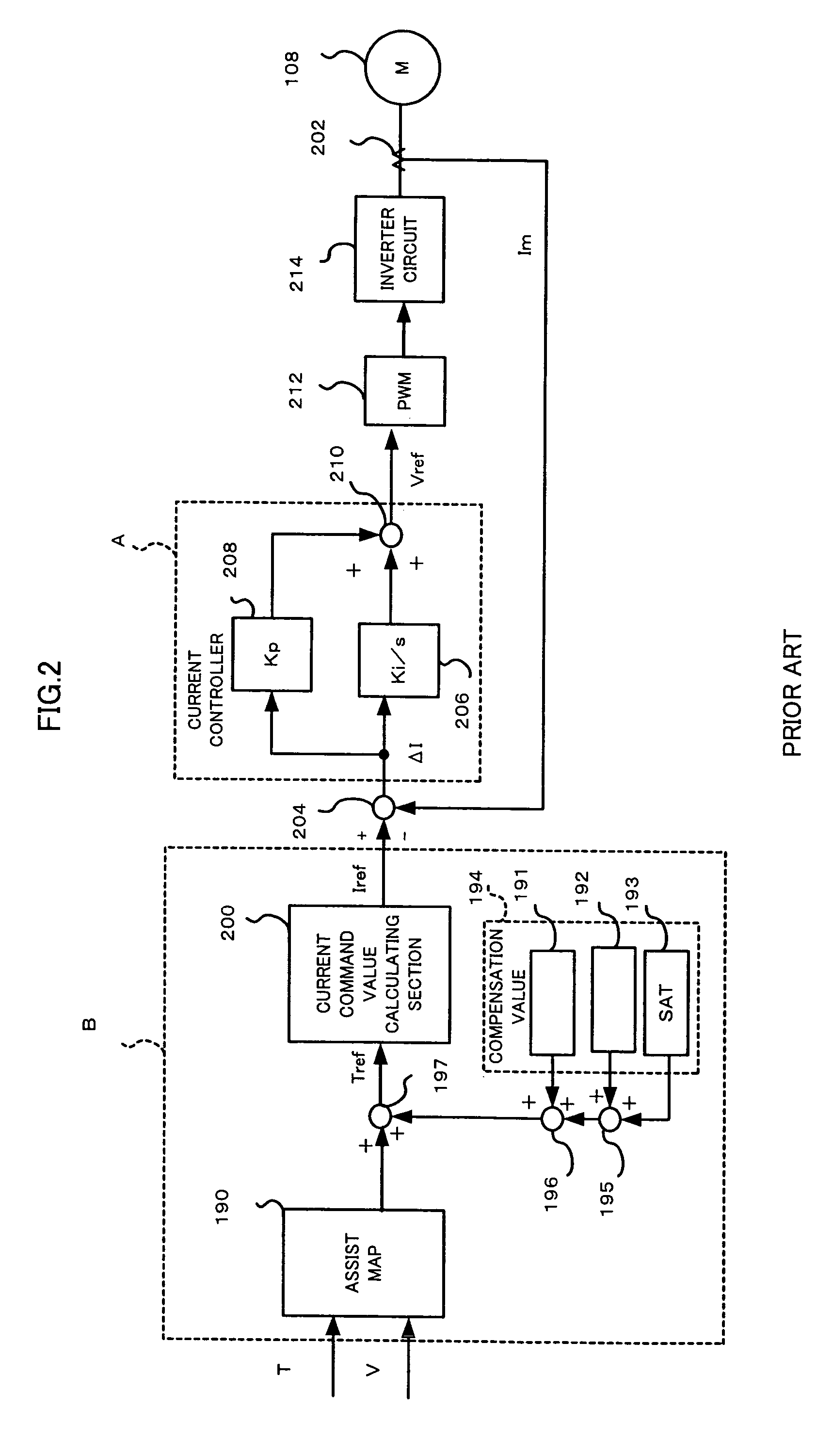
[0047]In FIG. 3, a current command value determining section B inputs a torque value T detected by a torque sensor 107, a vehicle speed V detected by a vehicle speed sensor and an auxiliary value therein, and determines a current command value Iref. Meanwhile, a motor current Im to be supplied to a motor 108 is detected by a current detector 202 and is inputted together with the current command value Iref to a subtracting section 204. The subtracting section 204 calculates their error ΔI=Iref−Im.

[0048]The error ΔI is inputted to a current controller A. In this example, the error ΔI is inputted to a proportional section 208 and a first order lag function section 10. An output from the proportional section 208 and an output from the first order lag functio...

embodiment-2

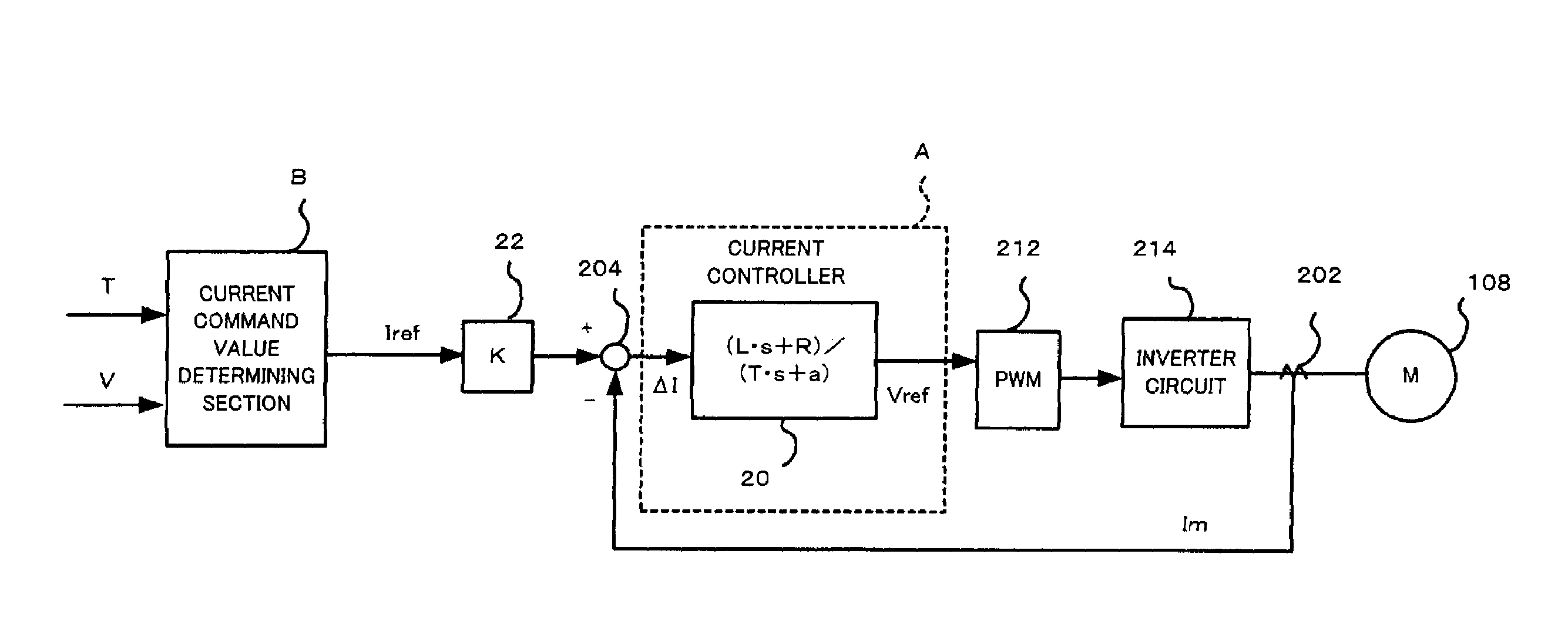
[0052]Another embodiment where the steady state gain of the current controller A is a finite value is explained below with reference to FIG. 4. In this embodiment, a lead / lag function is used as the function of the current controller A. A function (L·s+R) / (T·s+a) is used as one example of the lead / lag function. “L” designates an inductance value of the motor 108, “R” designates a resistance value of the motor 108, “T” designates a time constant and “a” designates a constant. The steady state gain Gad of the lead / lag function is expressed by the following equation 3.

[0053]Gad=lims->o⁢⁢(L·s+R) / (T·s+a)=R / a[Equation⁢⁢3]

[0054]The steady state gain Gad=R / a may be set so that the vibration and noise are not generated in the steering wheel in case of the steering holding state or the slow steering state of the steering wheel.

[0055]A constitution of the embodiment-2 is explained with reference to FIG. 4. The torque value T detected by the torque sensor 107, the vehicle speed V detected by...

embodiment-3

[0058]An embodiment-3 shown in FIG. 5 is an embodiment where a gain which corrects the feedback gain of the embodiment-2 is provided. That is to say, in the constitution of the embodiment-2 in FIG. 4, a gain section 22 having a gain “K” is arranged between the current command value determining section B and the subtracting section 204.

[0059]The gain of a current feedback control loop is theoretically “1 / (1+a)” which is smaller than “1”. Since the constant “a” is set to be as small as possible so that the vibration and noise are not generated, the gain “1 / (1+a)” becomes about “1”. In the case of the high-output electric power steering apparatus, since the motor current value is large, for example, a rated current becomes 100A, even when the constant “a” is, for example, “0.01”, the current error cannot be ignored. In the case where, therefore, the influence of the gain cannot be ignored, the gain section 22 is arranged so as to correct the gain K, thereby adjusting the influence of t...


PUM


Abstract

The present invention provides an excellent electric power steering apparatus in which torque ripple caused by a quantization error of a current control system generated in case of slow steering state and steering holding state, namely, vibration and noise on a steering wheel can be suppressed. A current controller in which a steady state gain of feedback control is a finite value is used so as to be capable of suppressing the vibration and noise. Further, according to the present invention, a smoothing filter is included in a current control system so that the quantization error is smoothed so that the torque ripple is suppressed.

Description

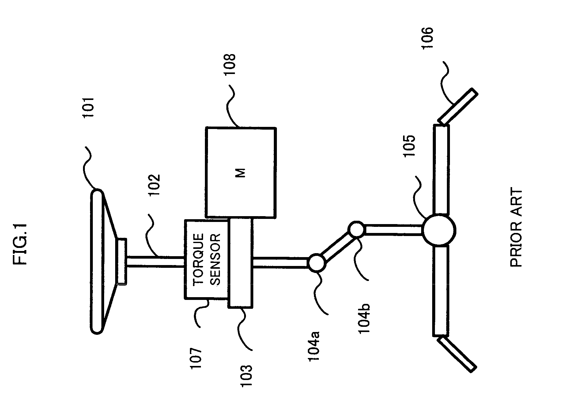
BACKGROUND OF THE INVENTION[0001]1. Field of the Invention[0002]The present invention relates to an electric power steering apparatus, and particularly to the electric power steering apparatus with less vibration of a steering wheel and less noises, and with satisfactory steering feeling. Further, the present invention relates to the electric power steering apparatus having satisfactory steering feeling in which vibration and noise (hereinafter, called also as “steering holding noise”) on a steering wheel in case of steering holding state can be reduced and a steering performance in a normal steering state (at the time of normal steering) can be secured.[0003]2. Prior Art[0004]Electric power steering apparatuses, which apply an assist torque to a steering apparatus of a vehicle by means of a rotation torque of a motor, apply the assist torque to a steering shaft or a rack shaft in such a manner a transmission mechanism such as gears or a belt applies a driving power of the motor via...

Claims


Application Information

Patent Timeline
Patent Type & Authority Patents(United States)
IPC IPC(8): H02P7/00
CPCB62D5/0463B62D5/0472
Inventor ENDO, SHUJIAOKI, YUHOMORI, KENJISAKAGUCHI, TORUNEJO, SAKAEOKAZAKI, HIDEAKIKOVUDHIKULRUNGSRI, LILIT
Owner NSK LTD
Learn More