Built multiple cam

Inactive Publication Date: 2007-04-05
THYSSENKRUPP PRESTA TECCENTER AG
View PDF6 Cites 5 Cited by
  • Summary
  • Abstract
  • Description
  • Claims
  • Application Information

AI Technical Summary

Benefits of technology

[0006] It is the object of the invention to provide a built-up multiple cam which can be produced cost-effectively and can be used in a flexible manner and which requires a small amount of installation space in the axial direction. In particular, it is intended to be joined to the support shaft of the camshaft with the aid of simple joining processes and also to be useable for built-up camshafts which are not pro

Problems solved by technology

The multiple cams which are known from DE 196 06 732 C2 have the disadvantage that the connection between the individual parts is comparatively wea

Method used


Image

  • Built multiple cam
  • Built multiple cam
  • Built multiple cam

Examples


Example

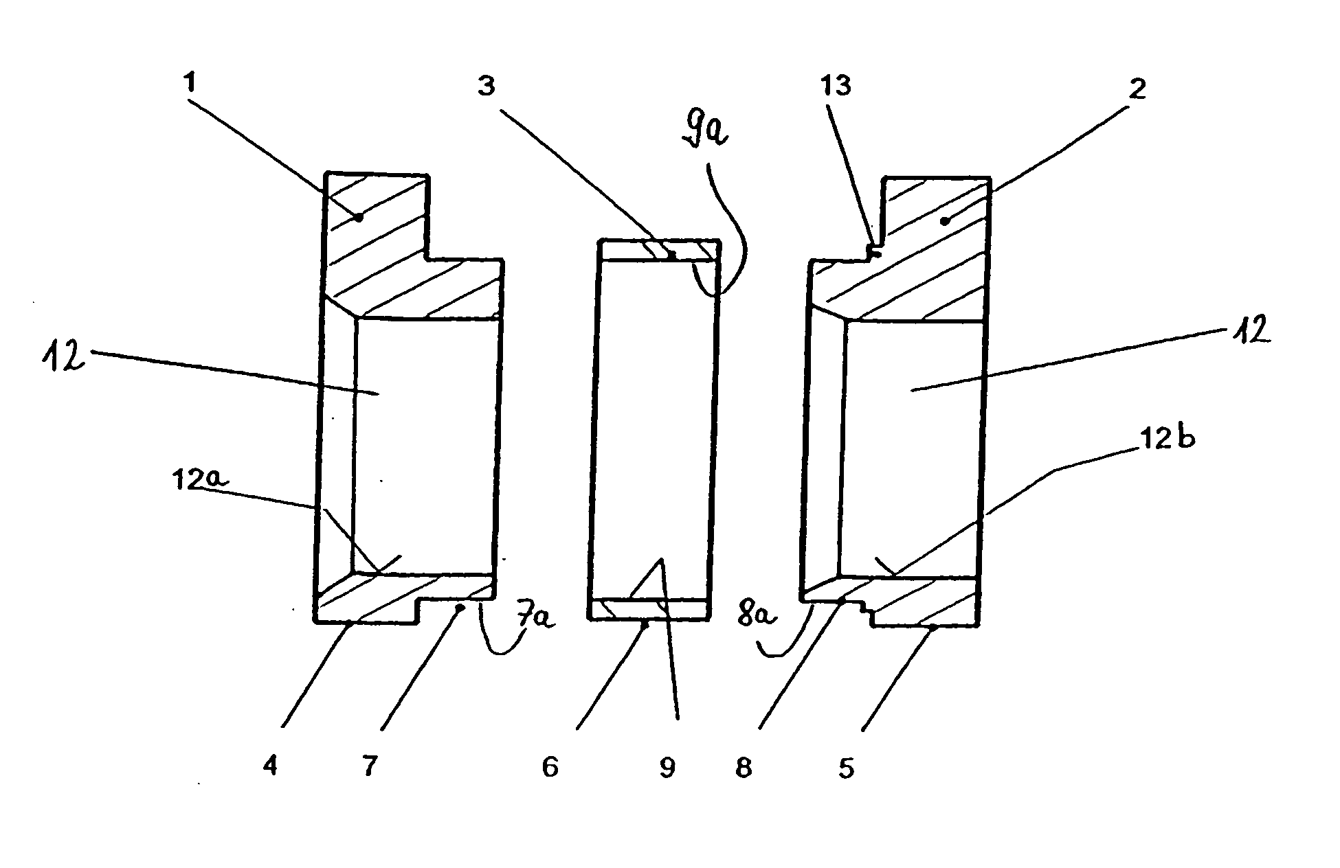
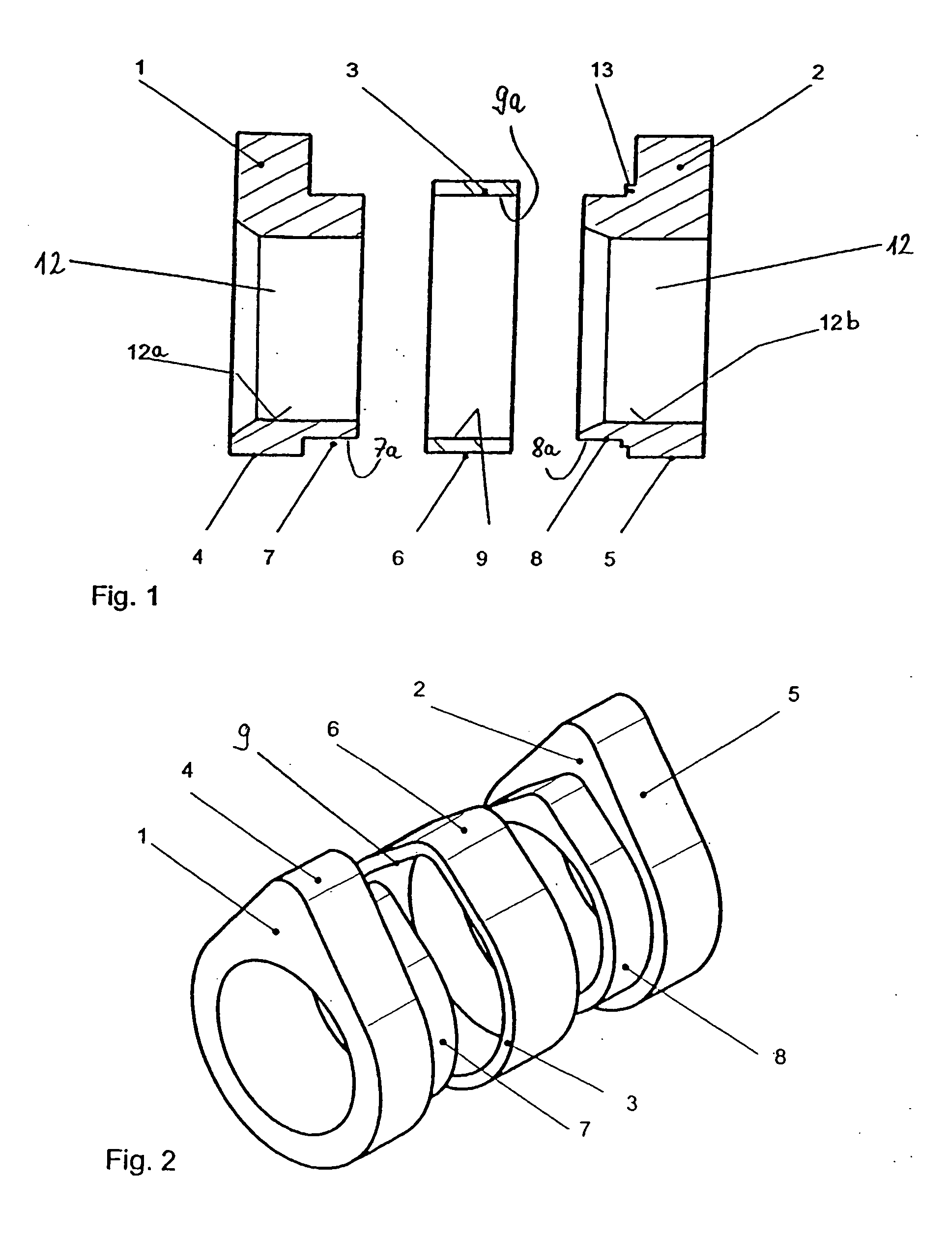
[0029]FIG. 1 illustrates a partial cam 1 which comprises a bore 12, an outer cam contour 4 and a joint contour 7. In a similar manner, the partial cam 2 comprises a bore 12, a cam contour 5 and a joint contour 8. In addition, the partial cam 2 is provided with a shoulder 13 which is integrally formed with the partial cam 2. The bores 12 of the partial cams 1 and 2 are identical in size. The ring 3 comprises an outer cam contour 6 and an inner contour 9 which comprises an inner surface 9a. If the individual parts illustrated in FIG. 1 are to be assembled to form a multiple cam, then the ring 3 is slid with its inner surface 9a over the outer surfaces 7a, 8a of the joint contours 7, 8. During assembly, an interference fit is formed between the inner surface 9a and the outer surfaces 7a, 8a of the joint contours 7, 8. In order to achieve a particularly strong interference fit, the outer surfaces 7a, 8a of the joint contours 7, 8 and / or the inner surface 9a of the ring 3 are provided wi...


PUM

PropertyMeasurementUnit
Angleaaaaaaaaaa
Radiusaaaaaaaaaa

Abstract

A built multiple cam is disclosed which can be produced at low cost and which can be used in a flexible manner and which requires a small amount of construction space in an axial direction. The built multiple cam comprises the following components: a first partial cam provided with a bore, a cam contour A and a joint contour which is arranged in axial proximity thereto and provided with an outer surface; a second partial cam provided with a bore, a cam contour A and a joint contour which is arranged in axial proximity thereto and provided with an outer surface; a ring which is provided with a cam contour B which is different from cam contour A and an inner contour having an inner surface, wherein the inner surface of the ring can be displaced towards the outer surfaces of the partial cams; and connections which act between the ring and the partial cam ensure a fixed connection between such components. Also disclosed is a method used to produce a built camshaft comprising at least one built multiple cam.

Description

BACKGROUND OF THE INVENTION [0001] The invention relates to a built-up multiple cam, a camshaft having at least one built-up multiple cam and to a method of producing a camshaft having at least one built-up multiple cam. [0002] The further development in the field of valve-controlled internal combustion engines places ever greater demands upon the camshafts utilised for controlling the valves. An important trend resides in the use of techniques for the variable control of the valve control times. Most recently, systems have become established, in which the valve lift is controlled by two mutually different cam contours, so that it is possible to switch between two different valve lifts. For this purpose, camshafts are used having multiple cams, on which at least two different cam contours are formed. The “VarioCam Plus” system which is utilised in vehicles produced by the company Porsche can be described as an example of this type of system. In the case of this system, so-called swi...

Claims


Application Information

Patent Timeline
IPC IPC(8): F01L1/04B23P11/00F01L1/047F16H53/02
CPCB23P11/00B23P2700/02Y10T29/49293F01L2001/0475F16H53/025F01L1/047F16H53/00F16H53/02
Inventor WALZ, THOMAS
Owner THYSSENKRUPP PRESTA TECCENTER AG
Why Eureka
Try Eureka