Power Tool

a power tool and power technology, applied in the direction of positive displacement liquid engines, pressure lubrication, combustion engines, etc., can solve the problems of high switching frequency, achieve excellent diaphragm pump conveying capacity, reduce switching frequency, and reduce the effect of switching frequency

Inactive Publication Date: 2007-04-05
ANDREAS STIHL AG & CO KG
View PDF15 Cites 0 Cited by
  • Summary
  • Abstract
  • Description
  • Claims
  • Application Information

AI Technical Summary

Benefits of technology

[0008] Preferably, the valve diaphragm is provided with valve elements that are arranged at the suction (vacuum) side or intake side of the diaphragm pump as well as with valve elements that are arranged at the pressure side of the diaphragm pump. In this way, a compact configuration of the diaphragm pump results and only one valve diaphragm is required. Preferably, the number of the valve elements on the vacuum side is greater than the number of valve elements on the pressure side. It is provided that a plurality of valve elements are formed within the valve membrane so that a higher conveying volume is realized at minimal switching times of the valve elements. A simple configuration results when the valve elements are formed by U-shaped slots in the valve diaphragm.
[0009] It is provided that the pump diaphragm is loaded by a pressure spring that counteracts the underpressure (vacuum) in the crankcase. By means of the pressure spring the operating point of the pump can be shifted. When underpressure is present in the crankcase, not only the medium to be conveyed is sucked in but the pressure spring is tensioned also. The pump stroke is realized as a result of the overpressure in the crankcase and as a result of the force of the pressure spring. In this way, an excellent conveying capacity of the diaphragm pump can be obtained.
[0010] Expediently, the diaphragm pump has a first valve plate and a second valve plate wherein the first valve plate is arranged on the pump diaphragm and the valve diaphragm is arranged between the first and second valve plates. In this way, a simple and compact configuration of the diaphragm pump results. Preferably, in the first valve plate intake openings and pressure openings are provided while in the second valve plate only intake openings are provided. Accordingly, during the intake stroke, the medium flows thus through the first valve plate as well as through the second valve plate. At the pressure side, the medium flows only through the second valve plate. From here, the medium exits the diaphragm pump. In this way, the pressure loss at the pressure side is reduced.
[0011] In order to keep the pressure pulsation minimal at the intake side, the diaphragm pump is provided with a compensation chamber at the vacuum side (suction side) of the diaphragm pump. Preferably, on the side of the second valve plate that is facing away from the first valve plate a lid is arranged and between the lid and the second valve plate a compensation chamber is arranged. In this connection, the compensation chamber is in particular delimited by a compensation diaphragm that is arranged between the lid and the second valve plate. In this way, the pulsations at the vacuum side can be smoothed in a constructively simple way. By providing a diaphragm that provides a sealing function between the first and the second valve plates as well as between the second valve plate and the lid, additional seals are not needed. In this way, a minimal number of individual parts is present. Preferably, the lid has at least one compensation opening that enables pressure compensation between the compensation chamber and the environment. It is provided that the intake connector of the diaphragm pump opens into the compensation chamber and the pressure connector opens into the pressure chamber provided between the valve diaphragm and the second valve plate.
[0012] Preferably, the power tool is a spraying device and the pump that is driven by the fluctuating pressure in the crankcase serves for conveying the medium to be sprayed. The pump has a simple and compact configuration and can be sealed in a simple way. Since in the configuration of the pump as a diaphragm pump only the diaphragms and the valve plates come into contact with the medium to be sprayed, it is possible in a simple way to provide a pump that is resistant to the media to be pumped.
[0013] In order to take full advantage of the fluctuating crankcase pressure, the power tool has a second pump, especially a diaphragm pump for conveying fuel to the internal combustion engine; the second pump (fuel pump) is also driven by the fluctuating crankcase pressure. In this way, for the pump for conveying the fuel as well as for the pump for conveying a further or additional medium, e.g. a medium to be sprayed, a simple configuration is provided. Accordingly, the power tool as a whole is of a simple configuration.

Problems solved by technology

The minimal size of the individual valve elements results in minimal sluggishness and thus a high switching frequency.

Method used


Image

  • Power Tool
  • Power Tool
  • Power Tool

Examples


Embodiment Construction

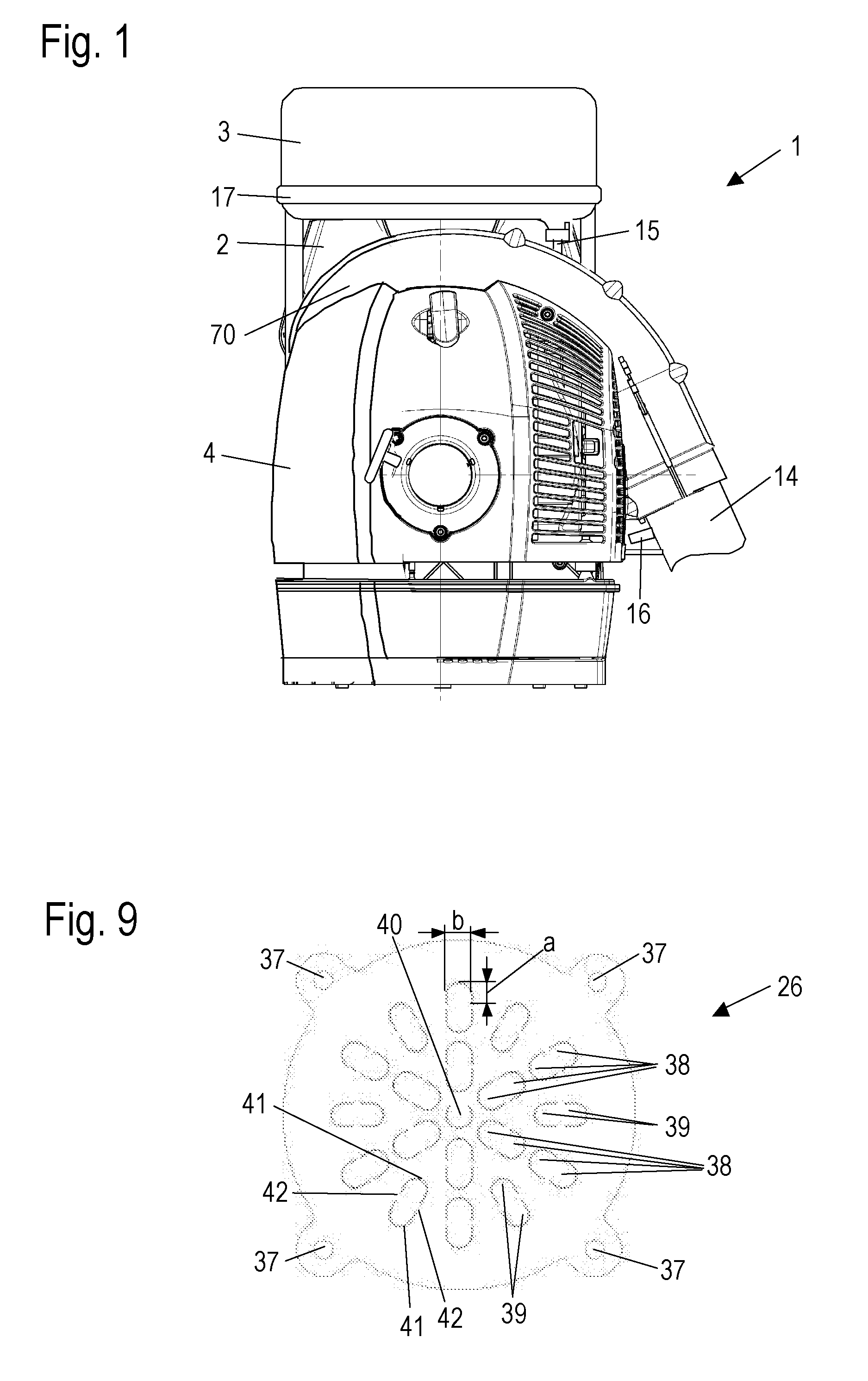
[0025] The spraying device 1 illustrated in FIG. 1 is configured as a backpack-type power tool. The spraying device 1 has a carrying frame 2 to allow the operator to carry the power tool on his back; the housing 4 is secured to the carrying frame 2. The carrying frame 2 has a frame part 17 schematically illustrated in FIG. 1 on which a tank 3 is arranged. The tank 3 serves for containing a medium to be sprayed, for example, a plant protection medium or the like, that is to be dispensed by means of the spraying device 1. The tank 3 is connected by means of a supply line 15 to a pump, not illustrated in FIG. 1. The pump conveys the medium to be sprayed out of the tank 3 through conveying line 16 to a blower pipe 14. The spraying device 1 generates an air flow in the blower pipe 14 that atomizes the medium to be sprayed and supplies it to the plants to be treated.

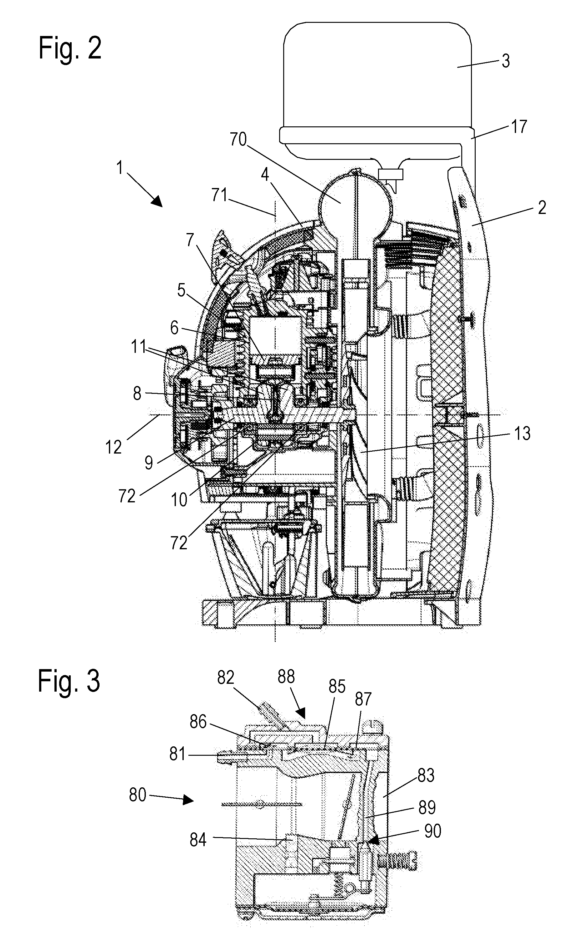
[0026] As illustrated in section in FIG. 2, the spraying device 1 has an internal combustion engine 5 arranged in the housi...


PUM


Abstract

A power tool has an internal combustion engine having a crankcase and a reciprocating piston. The interior of the crankcase is delimited by the reciprocating piston. A pump for conveying a fluid is provided, wherein the pump is driven by a fluctuating pressure in the crankcase. The pump conveys a foreign fluid that is different from an operating medium of the internal combustion engine. The power tool is a spraying device and the pump conveys a medium to be sprayed.

Description

BACKGROUND OF THE INVENTION [0001] The invention relates to a power tool, particularly a spraying device, having an internal combustion engine provided with a crankcase. The interior of the crankcase is delimited by a reciprocating piston. The power tool has a pump for conveying a fluid, the pump being driven by the fluctuating pressure within the crankcase. [0002] U.S. Pat. No. 4,903,655 discloses a diaphragm pump for a power tool that is driven by the fluctuating crankcase pressure of an internal combustion engine. The diaphragm pump serves for conveying the fuel to the internal combustion engine. The check valves at the vacuum side and at the pressure side of the diaphragm pump are formed within the pump diaphragm. Since the pump diaphragm is small and the check valves have only a small flow cross-section, the conveying capacity of the diaphragm pump is minimal. [0003] In spraying devices a pump is required for conveying a medium to be sprayed. This pump is usually driven by the ...

Claims


Application Information

Patent Timeline
Patent Type & Authority Applications(United States)
IPC IPC(8): F02B41/00F01M1/04
CPCF04B43/06
Inventor ROSSKAMP, HEIKORAFFENBERG, MICHAELGEYER, WERNER
Owner ANDREAS STIHL AG & CO KG
Why Eureka
Try Eureka