Venturi geometry design for flow-generator patient circuit

a flow generator and flow geometry technology, applied in the field of breathing apparatus, can solve the problems of reducing the overall effectiveness and desirability of flow generators, limiting the amount of supply pressure that can be utilized in cpap therapy for certain patients, and requiring excessive supply pressure, so as to achieve efficient inhalation and efficient exhaustion of patient's mouth

Active Publication Date: 2007-04-05
VYAIRE MEDICAL 211 INC
View PDF30 Cites 100 Cited by
  • Summary
  • Abstract
  • Description
  • Claims
  • Application Information

AI Technical Summary

Benefits of technology

[0011] The present invention specifically addresses and alleviates the above referenced deficiencies associated with flow generators of the prior art. More particularly, the present invention is a universal interface that is adapted for providing continuous positive airway pressure (CPAP) with reduced supply gas pressure as compared to flow generators of the prior art. In this manner, the universal interface of the present invention minimizes risks posed by excessive pressure in the patient's airways.
[0012] More particularly, the universal interface of the present invention is specifically configured to operate with a standard ventilator at a maximum supply pressure of about 120 centimeters (cm) of H2O in order to deliver pressure to the patient of up to about 15 cm of H2O at a flow rate of up to about 12 liters / minute. Advantageously, the universal interface as presently constructed provides increased efficiency in that it operates with the reduced supply pressure while still providing a constant positive pressure within the patient's airways. Furthermore, the universal interface accomplishes the above with minimal pressure resistance during inhalation and exhalation phases of breathing at the patient.
[0013] Reduced operating pressure in the universal interface of the present invention is facilitated by including unique taper geometry within certain portions of the interface body. More specifically, the universal interface includes a pair of exhalation passageways and supply passageways which are each provided with a taper portion. The taper portion is specifically configured to minimize pressure resistance during inhalation and exhalation.
[0018] Each one of the supply passageways is configured to introduce pressurized gas into the patient passageways such as during the inspiration phase of the breathing cycle. A supply manifold may be integrally formed with the universal interface in order to supply pressure to the breathing passageways. The supply manifold may have the supply passageways extending therefrom which are configured to introduce pressurized gas to an interior of each of the supply passageways and, ultimately, into the patient passageways. Because the supply manifold is in fluid communication with the gas source via the supply tube, the supply manifold receives the pressurized gas therefrom and introduces the gas into the patient passageways via the pair of jet venturis. Notably, each one of the jet venturis include the tapered geometry for performance enhancement.
[0023] Because of the unique geometry (i.e., tapered geometry) of the jet venturis and the exhalation passageways, exhaled air from the patient may be efficiently exhausted from the patient's mouth. In addition, air may be efficiently inhaled due to the provision of supply gas originating from the supply manifold and passing through the jet venturis. The universal interface may further include a pressure passageway which is provided for the purpose of measuring pressure at the patient airways. In this regard, pressure transducers may be placed in fluid communication with the pressure passageway such that pressure of the patient may be measured.

Problems solved by technology

Although the use of such apparatus has generally proven to be suitable for their intended purposes, such prior art breathing apparatus possess certain design deficiencies which detract from their overall effectiveness and desirability.
Unfortunately, conventional ventilators typically operate at a lower pressure than the pressure required for CPAP therapy treatment.
Therefore, one design deficiency characterizing prior art flow generators is that such flow generators require the use of excessive supply pressure in order to create sufficient pressure at the patient.
However, federal standards limit the amount of supply pressure that can be utilized in CPAP therapy for certain patients.
As may be appreciated, dangerously high supply pressures as required in prior art flow generators may subject the patient to the risk of injury.
For example, high pressures within the patient airway can cause damage to lungs as well as other organs.
In addition, exposure to high pressure in the patient airway may result in other respiratory complications.
Another deficiency associated with prior art flow generators is that the requirement for excessive supply pressures requires a concomitant increased amount of power in order to generate the desired amount of patient pressure.
In this regard, prior art flow generators are relatively inefficient and unsafe when used in CPAP therapy.

Method used


Image

  • Venturi geometry design for flow-generator patient circuit
  • Venturi geometry design for flow-generator patient circuit
  • Venturi geometry design for flow-generator patient circuit

Examples


Embodiment Construction

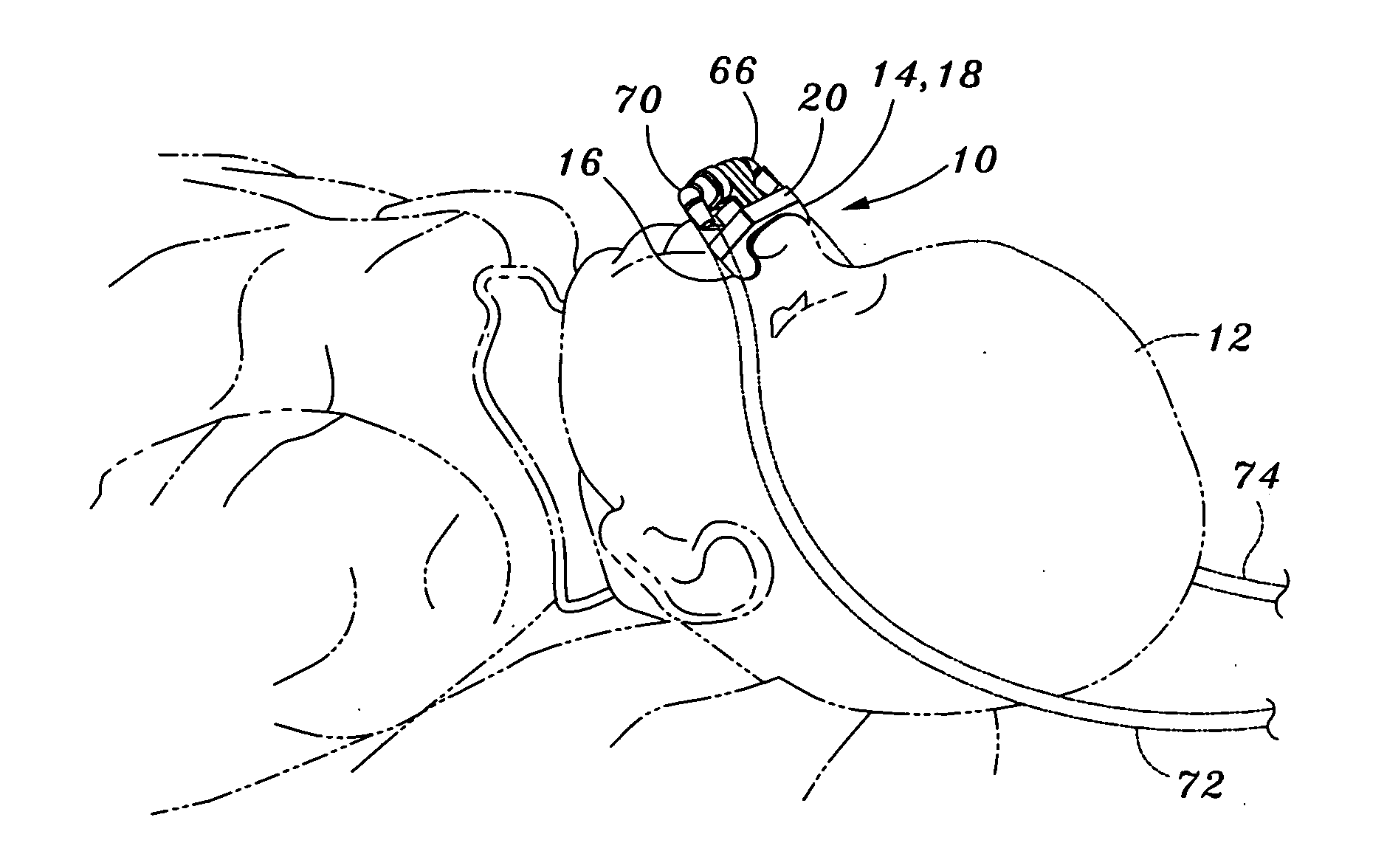
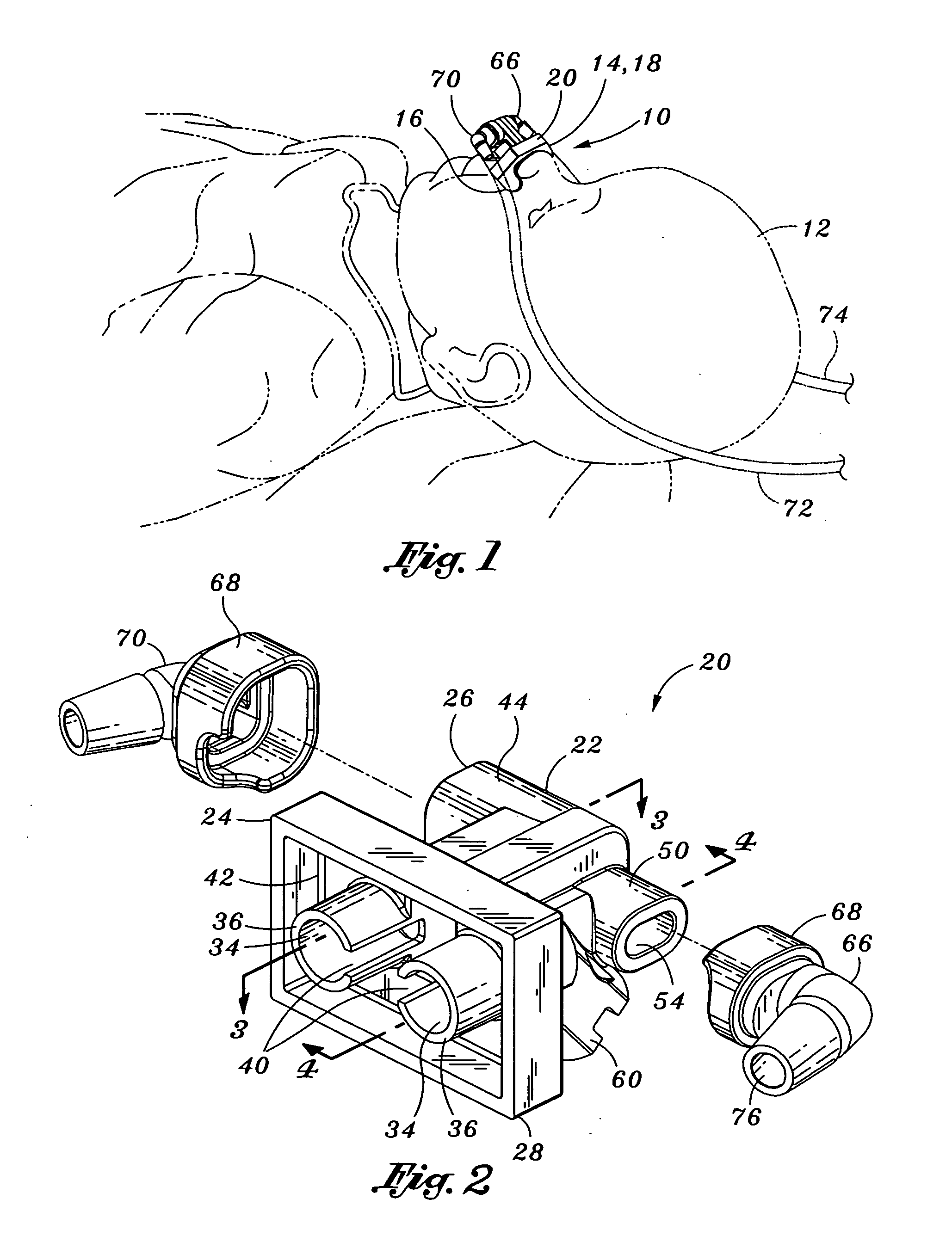
[0034] Referring now to the drawings wherein the showings are for purposes of illustrating preferred embodiments of the present invention only, and not for purposes of limiting the same, FIG. 1 perceptively illustrates the universal interface 20 as applied to an infant patient 12. The universal interface 20 includes a pressure tube 72 and a supply tube 74 attached on opposite sides of the universal interface 20 and extending around the patient's 12 head. As was mentioned above, the universal interface 20 of the present invention is specifically adapted to provide continuous positive airway pressure (CPAP) to the patient 12 at a reduced supply pressure when the universal interface 20 is used with a standard ventilator.

[0035] In particular, the universal interface 20 is specifically configured to operate at a pressure no greater than about 120 centimeters (cm) of H2O in order to deliver pressure to the patient of up to about 10 to 15 cm of H2O at a flow rate of up to about 12 liters / ...


PUM


Abstract

Provided is a universal interface adapted for providing continuous positive airway pressure to a patient when the interface is used with a standard ventilator. The interface is configured to operate at a supply pressure no greater than about 120 centimeters of H2O in order to deliver pressure to the patient of up to about 15 cm of H2O at a flow rate of up to about 12 liters / minute. The universal interface may comprise an interface body having a space pair of breathing passageways intersecting a corresponding of supply passageways. Each one of the breathing passageways is comprised of a patient passageway and an exhalation passageway. Each one of the supply passageways includes a jet venturi having a taper portion. Each one of the exhalation passageways includes a taper portion which tapers outwardly along a direction from the patient passageway toward the exhalation passageway.

Description

CROSS-REFERENCE TO RELATED APPLICATIONS [0001] (Not Applicable) STATEMENT RE: FEDERALLY SPONSORED RESEARCH / DEVELOPMENT [0002] (Not Applicable) BACKGROUND OF THE INVENTION [0003] The present invention relates generally to breathing apparatus and, more particularly, to a universal interface for a breathing apparatus which is specifically adapted to provide continuous positive airway pressure (CPAP) when the interface is used with a standard ventilator and which further is constructed with unique geometries to increase stagnation pressure (i.e., patient pressure) with minimal supply pressure as well as reduced exhalation resistance in order to improve the work of breathing. [0004] The use of breathing apparatus upon respiratory-impaired patients is well known. Generally, such apparatuses assist in patient breathing by allowing proper exchange of inhaled and exhaled gas while providing pressurized gasses to a patient's lungs so as to prevent lung collapse. In this manner, conventional b...

Claims


Application Information

Patent Timeline
Patent Type & Authority Applications(United States)
IPC IPC(8): A61M16/00
CPCA61M16/0666A61M16/0012A61M16/0858
Inventor DUQUETTE, STEVENSTENZLER, ALEXHAN, STEVE
Owner VYAIRE MEDICAL 211 INC
Why Eureka
Try Eureka