Freewheel coupling

Inactive Publication Date: 2007-04-05
SCHAEFFLER TECH AG & CO KG
View PDF5 Cites 8 Cited by
  • Summary
  • Abstract
  • Description
  • Claims
  • Application Information

AI Technical Summary

Benefits of technology

[0003] The invention is based on the objective of providing a freewheel coupling, which distingui...

Problems solved by technology

Second, there is the possibility of transferring a static load acting in the radial direction from the inner ring...

Method used


Image

  • Freewheel coupling
  • Freewheel coupling
  • Freewheel coupling

Examples


Embodiment Construction

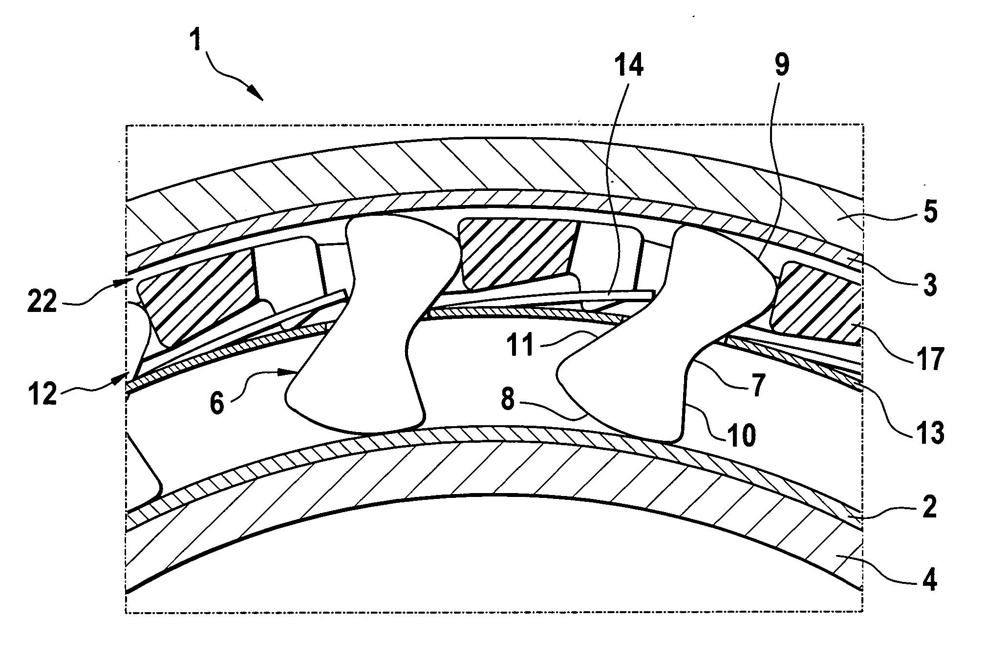
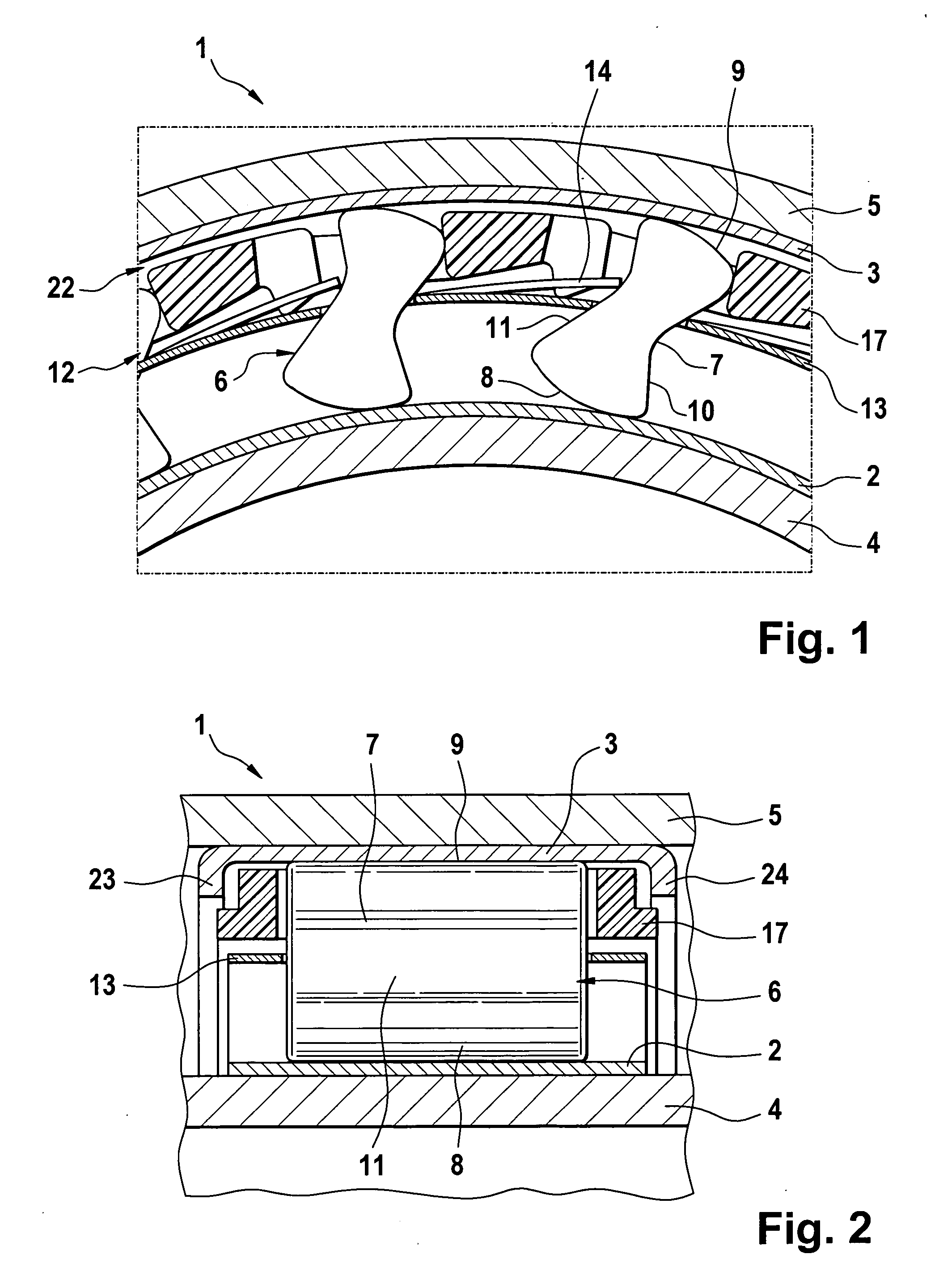
[0012] In simplified cross-sectional representations, FIGS. 1 and 2 show a freewheel coupling 1 with a bearing inner ring 2 and a bearing outer ring 3, which are constructed as sleeves formed using a non-cutting method, similar to a sleeve of a needle bearing. Accordingly, the outer surface of the bearing inner ring 2 and also the inner surface of the bearing outer ring 3 are configured as roller bearing tracks with a surface hardness of at least 670 HV. While the bearing inner ring 2 is locked in rotation on a shaft 4, the bearing outer ring 3 is pressed into the bore of a connection part 5. The press fit is sufficiently stable to prevent wandering of the bearing outer ring 3, which, in proper operation, can be exposed to both compression and tension loads. The function of the shown freewheel coupling 1 corresponds to the function of a conventional clamping body freewheel coupling, as described, for example, in DE 103 10 225 A1.

[0013] The freewheel function is created by clamping ...


PUM


Abstract

A freewheel coupling (1) is provided having a gap (12) formed between a bearing inner ring (2) and a bearing outer ring (3). At least one of the bearing rings (1, 2) is constructed as a sleeve formed using a non-cutting method. Clamping bodies (6) are arranged in the gap (12) and have a throat (7). A spring band (13) with spring tongues (14), which are aligned tangentially, and which can be deflected in the radial direction, contact the clamping bodies (6) in the area of the throats (7). A cage (17) with recesses (18) that holds the clamping bodies (6) is arranged radially outside of the spring band (13) in the gap (12).

Description

FIELD OF THE INVENTION [0001] The invention relates to a freewheel coupling or overrunning clutch with clamping elements, which are arranged in a gap between a bearing inner ring and a bearing outer ring and which are guided in recesses of a cage, with a continuous spring band being provided for spring mounting of the clamping elements. BACKGROUND OF THE INVENTION [0002] A freewheel coupling of the above-noted type is known, for example, from DE 80 14 018 U1. This freewheel coupling has a sleeve as a bearing outer ring, which can be embodied like a needle bearing sleeve surrounding the bearing needles. The bearing outer ring is suitable for pressing into a bore of a part, in which the freewheel coupling is to be mounted. The clamping elements of the freewheel coupling are secured against falling inwardly out of position, in that cage pockets guiding the clamping elements converge in the direction towards the shaft. The clamping elements are not secured from falling outwardly out of ...

Claims


Application Information

Patent Timeline
IPC IPC(8): F16D41/20
CPCF16D41/07
Inventor STRAUB, FRANKALTMANN, FRIEDER
Owner SCHAEFFLER TECH AG & CO KG
Why Eureka
Try Eureka