Method and apparatus for screening kaolin

a screening method and kaolin technology, applied in the direction of sieving, solid separation, screening, etc., can solve the problems of poor suitability for the efficient separation of very fine particles from filtrates, and often less preferred vibrating screening apparatus, etc., and achieve the effect of facilitating length customization

a screening method and kaolin technology, applied in the direction of sieving, solid separation, screening, etc., can solve the problems of poor suitability for the efficient separation of very fine particles from filtrates, and often less preferred vibrating screening apparatus, etc., and achieve the effect of facilitating length customization

US20070074998A1Inactive Publication Date: 2007-04-05LANGNER HERBERT GUNTHER JOACHIM

Image

  • Method and apparatus for screening kaolin
  • Method and apparatus for screening kaolin
  • Method and apparatus for screening kaolin

Examples


Embodiment Construction

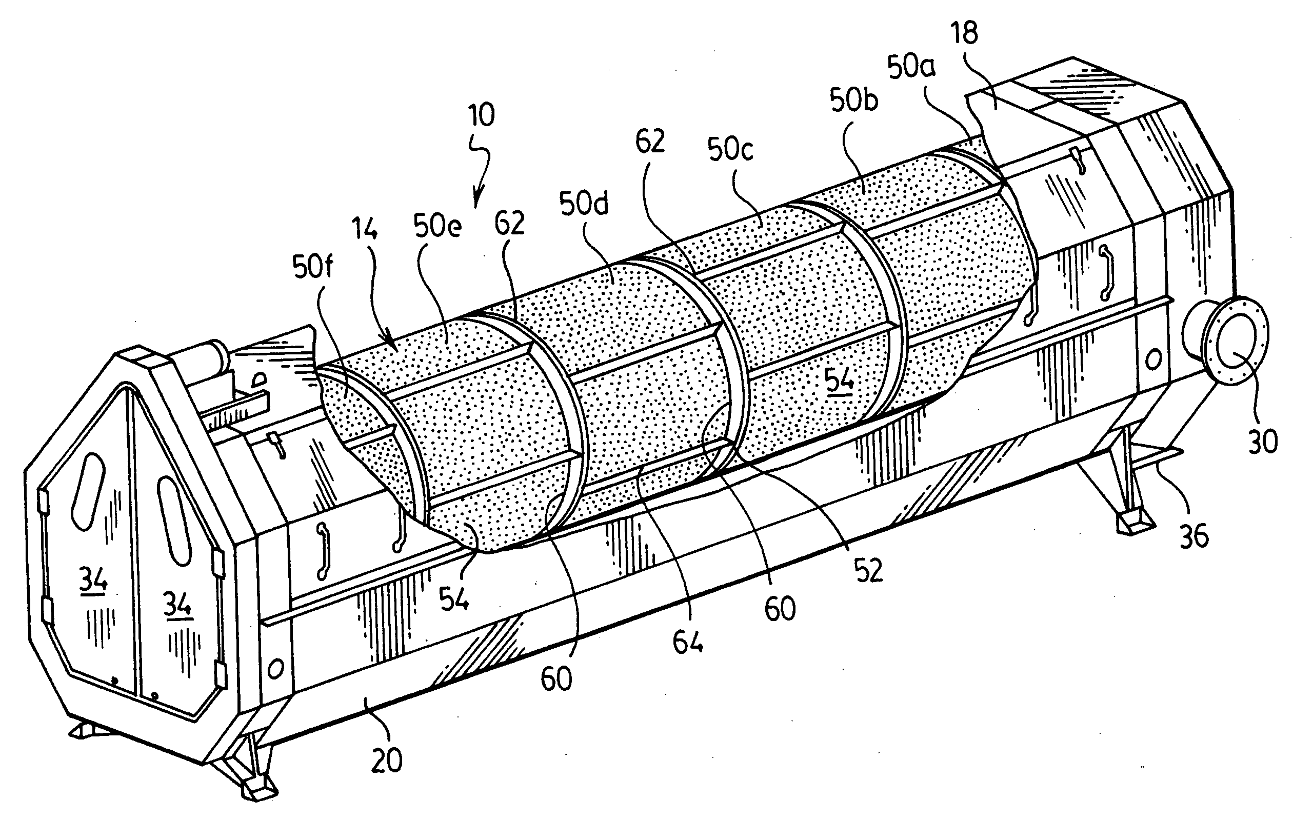
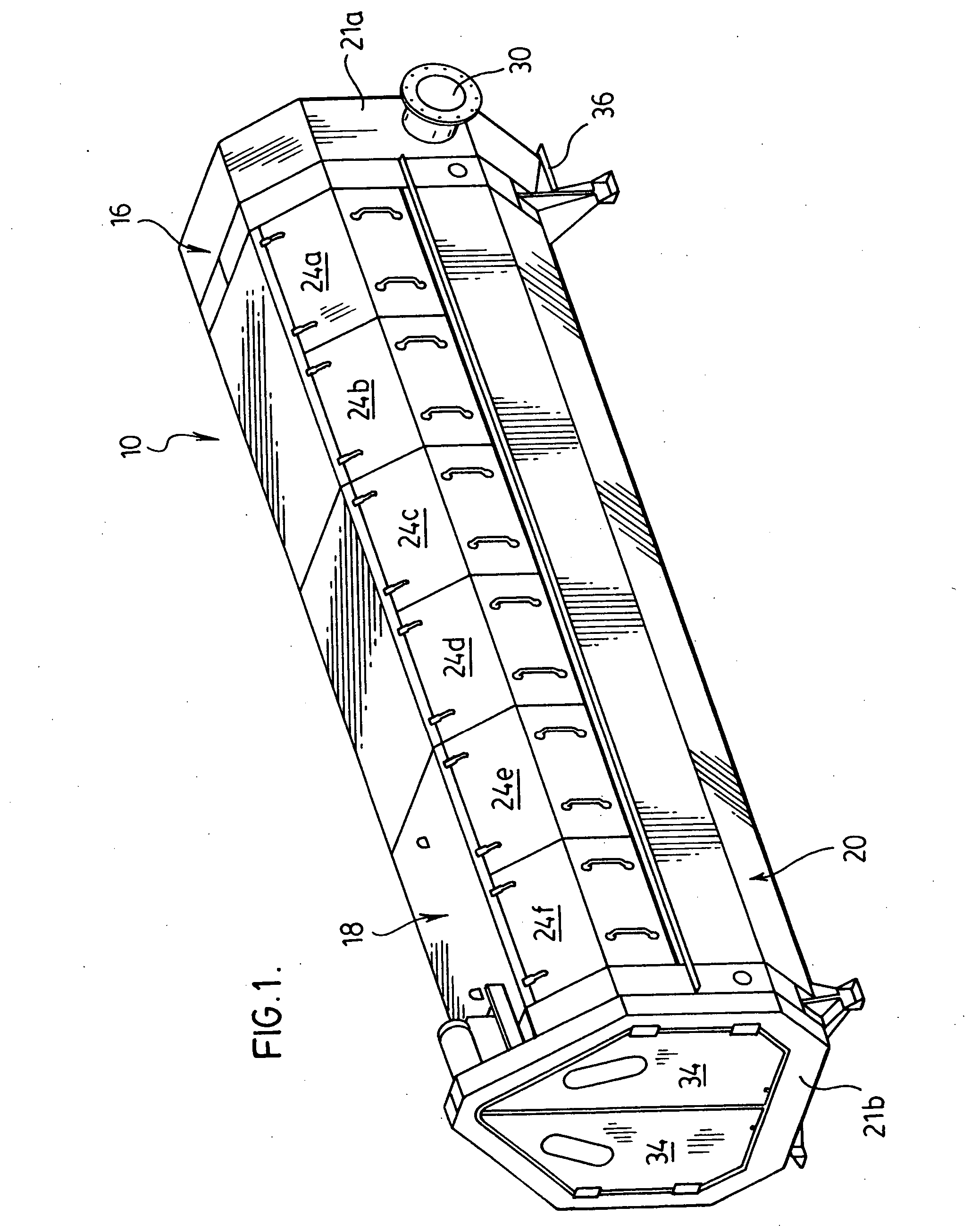
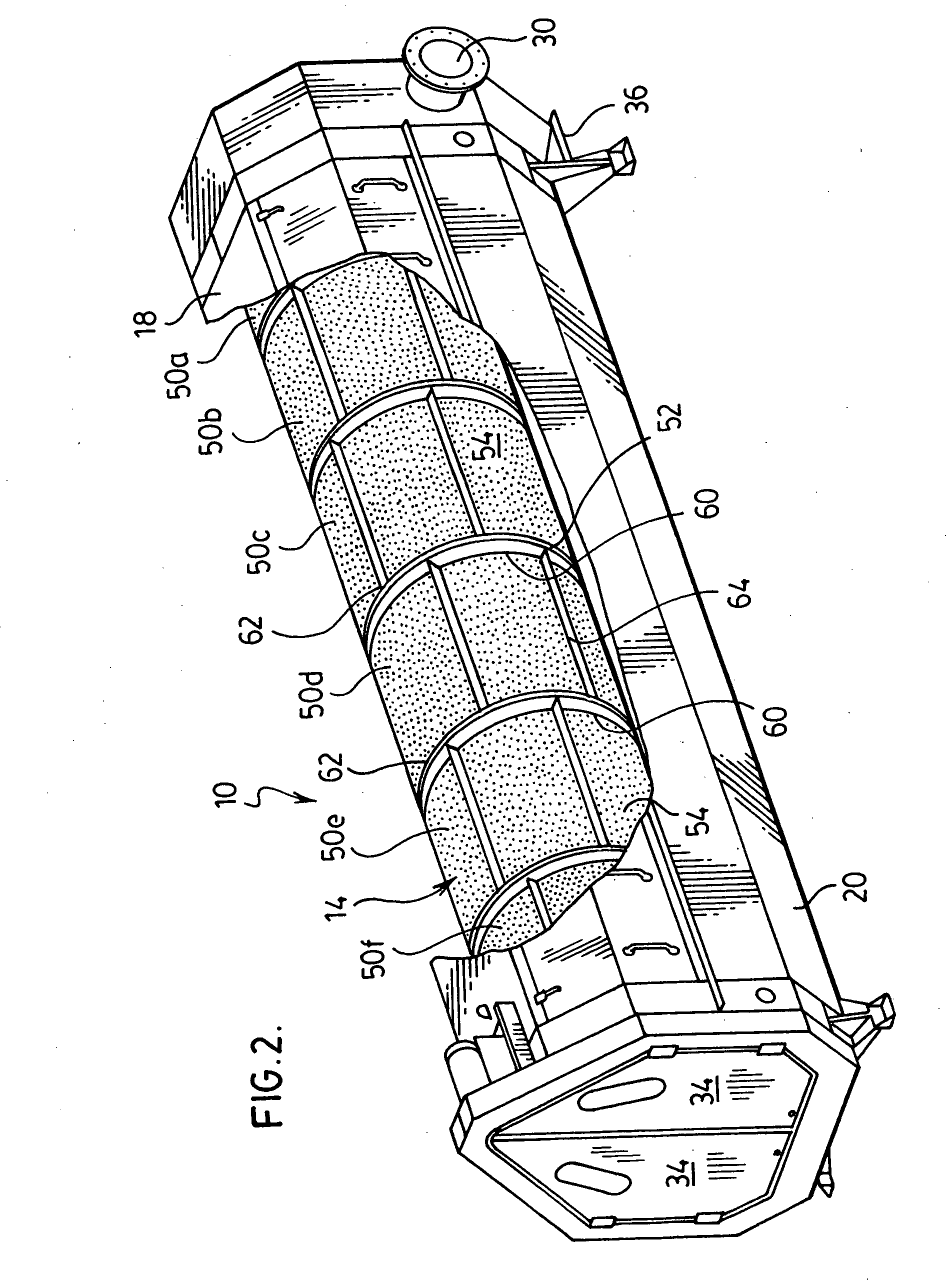
[0046] Reference is made first to FIGS. 1 and 2 which show a pictorial view of a rotary screening apparatus 10 for use in the classification of kaolin solids from an influent slurry in accordance with a preferred embodiment of the present invention. The screening apparatus includes an elongated hollow screening cylinder 14 (shown in the partially cut away view of FIG. 2) which is used to separate kaolin solids and filtrate from the slurry, and a containment housing 16.

[0047] The screening cylinder 14 has an overall diameter of between about 0.7 to 1.5 meters, and a longitudinal length of between about 5 and 8 meters, and more preferably about 6 meters.

[0048] As shown best in FIGS. 1 and 3 to 5 the containment housing 16 is formed as a generally two-piece casing which includes a cover 18, a lower spray shield 20 and a pair of end bulk heads 21a, 21b which are used to provide closed ends of the housing 16. The cover 18 and spray shield 20 have a size selected relative to the screeni...


PUM


Abstract

A rotary screening device is disclosed which includes a rotating cylinder formed from a number of coaxially aligned modular screening sections. Each cylindrical section having an inlet end, an outlet end and a cylindrical wall formed from a plurality of detachable screen panels each presenting a screening surface. The outlet end of a first cylinder section being secured in coaxial alignment with the inlet end of the next adjacent cylindrical section secured. The cylinder being rotatably supported on wheels within a containment housing which extends about the radial surfaces of the cylinder.

Description

SCOPE OF THE INVENTION [0001] The present invention is directed to a rotary screening apparatus for separating solids from filtrate in an influent stream, and more particularly a rotary screening apparatus having a screening cylinder formed from one or more modular cylindrical drum sections comprised of a cylindrical frame and one or more replaceable screen panels. BACKGROUND OF THE INVENTION [0002] Screening devices which incorporate rotating vibrating screens are well known for use in increasing the solid content of municipal sewage, sludge treatment, and food processing. Conventional rotating screening screens typically incorporate a hollow screening cylinder which is rotatably mounted within a containment housing in a generally upwardly inclined horizontal orientation on support wheels or a roller mechanism. The screening cylinder is journalled for rotation about its upwardly inclined axis. Influent to be screened is fed into the interior of the rotating cylinder at its lower en...

Claims


Application Information

Patent Timeline
05 Apr 2007
Publication
US20070074998A1
IPC
B07B1/18
CPC
B07B1/22; B07B1/4645; B07B1/469
Inventors
LANGNER, HERBERT GUNTHER JOACHIM